NTHS0603N10N1502JE Vishay, NTHS0603N10N1502JE Datasheet - Page 54
NTHS0603N10N1502JE
Manufacturer Part Number
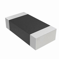
NTHS0603N10N1502JE
Description
THERMISTOR NTC 15K OHM 5% 0603
Manufacturer
Vishay
Series
NTHSr
Specifications of NTHS0603N10N1502JE
Resistance In Ohms @ 25°c
15K
Resistance Tolerance
±5%
B Value Tolerance
±3%
B25/75
3500K
Mounting Type
Surface Mount
Package / Case
0603 (1608 Metric)
Lead Free Status / RoHS Status
Lead free by exemption / RoHS Compliant
B0/50
-
B25/50
-
B25/85
-
B25/100
-
Operating Temperature
-
Power - Max
-
Lead Length
-
Lead Free Status / Rohs Status
Lead free / RoHS Compliant
Other names
541-1114-2
Available stocks
Company
Part Number
Manufacturer
Quantity
Price

Part Number:
NTHS0603N10N1502JE
Manufacturer:
VISHAY/威世
Quantity:
20 000


54
Legend
X = Don’t care.
RA = Address of the memory location to be read.
SA = Sector Address. Any address that falls within a specified sector. See
Tables
Notes
1. All values are in hexadecimal.
2. Shaded cells indicate read cycles.
3. Address and data bits not specified in table, legend, or notes are don’t
4. Writing incorrect address and data values or writing them in the improper
5. Entry commands are required to enter a specific mode to enable
6. No unlock or command cycles required when bank is reading array data.
cares (each hex digit implies 4 bits of data).
sequence may place the device in an unknown state. The system must
write the reset command to return the device to reading array data.
instructions only available within that mode.
8.2–8.8
Command Sequence
Command Set Entry
(Note 5)
Program
Read
Command Set Exit
(Note 7)
Command Set Entry
(Note 5)
Program
Read
Unlock
Command Set Exit
(Note 7)
Command Set Entry
(Note 5)
PPB Program
All PPB Erase
(Notes 11, 12)
PPB Status Read
Command Set Exit
(Note 7)
Command Set Entry
(Note 5)
PPB Lock Bit Set
PPB Lock Bit Status
Read
Command Set Exit
(Note 7)
Command Set Entry
(Note 5)
DYB Set
DYB Clear
DYB Status Read
Command Set Exit
(Note 7)
for sector address ranges.
(Notes)
(Note 6)
(Note 9)
(Note 10)
(Note 6)
(Note 8)
(Note 11)
11
3
2
1
2
3
2
8
2
3
2
2
1
2
3
2
1
2
3
2
2
1
2
Addr
AAA
XXX
XXX
AAA
XXX
AAA
XXX
XXX
XXX
AAA
XXX
XXX
XXX
AAA
XXX
XXX
XXX
XX
SA
SA
00
00
07
00
05
1st/8th
Table 10.4 Sector Protection Commands (x8)
PWD0
PWD7
PWD5
RD(0)
RD(0)
RD(0)
Data
Data
AA
A0
AA
A0
AA
A0
AA
A0
AA
A0
A0
90
25
90
80
90
90
90
PWAx
S29GL-N MirrorBit
Addr
XXX
XXX
XXX
XXX
XXX
555
555
555
555
555
XX
SA
XX
SA
SA
01
00
06
00
2nd/9th
PWD1
PWD6
PWDx
Data
Data
55
00
55
03
00
55
00
30
00
55
00
00
55
00
01
00
D a t a
Addr
AAA
AAA
AAA
AAA
AAA
02
00
07
®
3rd/10th
PWA = Password Address. Address bits A1 and A0 are used to select each 16-
bit portion of the 64-bit entity.
PWD = Password Data.
RD(0) = DQ0 protection indicator bit. If protected, DQ0 = 0. If unprotected,
DQ0 = 1.
7. Exit command must be issued to reset the device into read mode; device
8. Entire two bus-cycle sequence must be entered for each portion of the
9. Full address range is required for reading password.
10. Password may be unlocked or read in any order. Unlocking requires the full
11. ACC must be at V
12. “All PPB Erase” command pre-programs all PPBs before erasure to prevent
Flash Family
may otherwise be placed in an unknown state.
password.
password (all seven cycles).
over-erasure.
Bus Cycles (Notes 2–5)
PWD2
PWD0
PWD7
Data
C0
E0
40
60
50
S h e e t
Addr
03
01
00
4th/11th
IH
PWD3
PWD1
Data Addr
29
when setting PPB or DYB.
04
02
5th
S29GL-N_01_12 October 29, 2008
PWD4
PWD2
Data
Addr
05
03
6th
PWD5
PWD3
Data
Addr
06
04
7th
PWD6
PWD4
Data
Related parts for NTHS0603N10N1502JE
Image
Part Number
Description
Manufacturer
Datasheet
Request
R

Part Number:
Description:
357-036-542-201 CARDEDGE 36POS DL .156 BLK LOPRO
Manufacturer:
Vishay
Datasheet:
Part Number:
Description:
357-036-542-201 CARDEDGE 36POS DL .156 BLK LOPRO
Manufacturer:
Vishay
Datasheet:
Part Number:
Description:
357-036-542-201 CARDEDGE 36POS DL .156 BLK LOPRO
Manufacturer:
Vishay
Datasheet:
Part Number:
Description:
357-036-542-201 CARDEDGE 36POS DL .156 BLK LOPRO
Manufacturer:
Vishay
Datasheet:
Part Number:
Description:
357-036-542-201 CARDEDGE 36POS DL .156 BLK LOPRO
Manufacturer:
Vishay
Datasheet:
Part Number:
Description:
357-036-542-201 CARDEDGE 36POS DL .156 BLK LOPRO
Manufacturer:
Vishay
Datasheet:
Part Number:
Description:
357-036-542-201 CARDEDGE 36POS DL .156 BLK LOPRO
Manufacturer:
Vishay
Datasheet:
Part Number:
Description:
357-036-542-201 CARDEDGE 36POS DL .156 BLK LOPRO
Manufacturer:
Vishay
Datasheet:
Part Number:
Description:
357-036-542-201 CARDEDGE 36POS DL .156 BLK LOPRO
Manufacturer:
Vishay
Datasheet:
Part Number:
Description:
357-036-542-201 CARDEDGE 36POS DL .156 BLK LOPRO
Manufacturer:
Vishay
Datasheet:
Part Number:
Description:
357-036-542-201 CARDEDGE 36POS DL .156 BLK LOPRO
Manufacturer:
Vishay
Datasheet:
Part Number:
Description:
357-036-542-201 CARDEDGE 36POS DL .156 BLK LOPRO
Manufacturer:
Vishay
Datasheet:
Part Number:
Description:
357-036-542-201 CARDEDGE 36POS DL .156 BLK LOPRO
Manufacturer:
Vishay
Datasheet:
Part Number:
Description:
357-036-542-201 CARDEDGE 36POS DL .156 BLK LOPRO
Manufacturer:
Vishay
Datasheet:
Part Number:
Description:
357-036-542-201 CARDEDGE 36POS DL .156 BLK LOPRO
Manufacturer:
Vishay
Datasheet: