NTHS0603N10N1502JE Vishay, NTHS0603N10N1502JE Datasheet - Page 43
NTHS0603N10N1502JE
Manufacturer Part Number
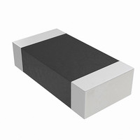
NTHS0603N10N1502JE
Description
THERMISTOR NTC 15K OHM 5% 0603
Manufacturer
Vishay
Series
NTHSr
Specifications of NTHS0603N10N1502JE
Resistance In Ohms @ 25°c
15K
Resistance Tolerance
±5%
B Value Tolerance
±3%
B25/75
3500K
Mounting Type
Surface Mount
Package / Case
0603 (1608 Metric)
Lead Free Status / RoHS Status
Lead free by exemption / RoHS Compliant
B0/50
-
B25/50
-
B25/85
-
B25/100
-
Operating Temperature
-
Power - Max
-
Lead Length
-
Lead Free Status / Rohs Status
Lead free / RoHS Compliant
Other names
541-1114-2
Available stocks
Company
Part Number
Manufacturer
Quantity
Price

Part Number:
NTHS0603N10N1502JE
Manufacturer:
VISHAY/威世
Quantity:
20 000


October 29, 2008 S29GL-N_01_12
10.4.2
10.4.3
Unlock Bypass Command Sequence
Write Buffer Programming
Any bit in a word cannot be programmed from 0 back to a 1. Attempting to do so may cause the device to
set DQ5=1, or cause DQ7 and DQ6 status bits to indicate the operation was successful. However, a
succeeding read shows that the data is still 0. Only erase operations can convert a 0 to a 1.
The unlock bypass feature allows the system to program words to the device faster than using the standard
program command sequence. The unlock bypass command sequence is initiated by first writing two unlock
cycles. This is followed by a third write cycle containing the unlock bypass command, 20h. The device then
enters the unlock bypass mode. A two-cycle unlock bypass mode command sequence is all that is required to
program in this mode. The first cycle in this sequence contains the unlock bypass program command, A0h;
the second cycle contains the program address and data. Additional data is programmed in the same
manner. This mode dispenses with the initial two unlock cycles required in the standard program command
sequence, resulting in faster total programming time.
show the requirements for the command sequence.
During the unlock bypass mode, only the Unlock Bypass Program and Unlock Bypass Reset commands are
valid. To exit the unlock bypass mode, the system must issue the two-cycle unlock bypass reset command
sequence. The first cycle must contain the data 90h. The second cycle must contain the data 00h. The device
then returns to the read mode.
Write Buffer Programming allows the system write to a maximum of 16 words/32 bytes in one programming
operation. This results in faster effective programming time than the standard programming algorithms. The
Write Buffer Programming command sequence is initiated by first writing two unlock cycles. This is followed
by a third write cycle containing the Write Buffer Load command written at the Sector Address in which
programming occurs. The fourth cycle writes the sector address and the number of word locations, minus
one, to be programmed. For example, if the system programs six unique address locations, then 05h should
be written to the device. This tells the device how many write buffer addresses are loaded with data and
therefore when to expect the Program Buffer to Flash command. The number of locations to program cannot
exceed the size of the write buffer or the operation aborts.
The fifth cycle writes the first address location and data to be programmed. The write-buffer-page is selected
by address bits A
The system then writes the remaining address/data pairs into the write buffer. Write buffer locations may be
loaded in any order.
The write-buffer-page address must be the same for all address/data pairs loaded into the write buffer. (This
means Write Buffer Programming cannot be performed across multiple write-buffer pages.) This also means
that Write Buffer Programming cannot be performed across multiple sectors. If the system attempts to load
programming data outside of the selected write-buffer page, the operation aborts.
Note that if a Write Buffer address location is loaded multiple times, the address/data pair counter is
decremented for every data load operation. The host system must therefore account for loading a write-buffer
location more than once. The counter decrements for each data load operation, not for each unique write-
buffer-address location. Note also that if an address location is loaded more than once into the buffer, the
final data loaded for that address is programmed.
Once the specified number of write buffer locations are loaded, the system must then write the Program
Buffer to Flash command at the sector address. Any other address and data combination aborts the Write
Buffer Programming operation. The device then begins programming. Data polling should be used while
monitoring the last address location loaded into the write buffer. DQ7, DQ6, DQ5, and DQ1 should be
monitored to determine the device status during Write Buffer Programming.
The write-buffer programming operation can be suspended using the standard program suspend/resume
commands. Upon successful completion of the Write Buffer Programming operation, the device is ready to
execute the next command.
The Write Buffer Programming Sequence can be aborted in the following ways:
Load a value that is greater than the page buffer size during the Number of Locations to Program step.
Write to an address in a sector different than the one specified during the Write-Buffer-Load command.
MAX
–A
4
. All subsequent address/data pairs must fall within the selected-write-buffer-page.
D a t a
S29GL-N MirrorBit
S h e e t
®
Flash Family
Table 10.1 on page 51
and
Table 10.3 on page 53
43
Related parts for NTHS0603N10N1502JE
Image
Part Number
Description
Manufacturer
Datasheet
Request
R

Part Number:
Description:
357-036-542-201 CARDEDGE 36POS DL .156 BLK LOPRO
Manufacturer:
Vishay
Datasheet:
Part Number:
Description:
357-036-542-201 CARDEDGE 36POS DL .156 BLK LOPRO
Manufacturer:
Vishay
Datasheet:
Part Number:
Description:
357-036-542-201 CARDEDGE 36POS DL .156 BLK LOPRO
Manufacturer:
Vishay
Datasheet:
Part Number:
Description:
357-036-542-201 CARDEDGE 36POS DL .156 BLK LOPRO
Manufacturer:
Vishay
Datasheet:
Part Number:
Description:
357-036-542-201 CARDEDGE 36POS DL .156 BLK LOPRO
Manufacturer:
Vishay
Datasheet:
Part Number:
Description:
357-036-542-201 CARDEDGE 36POS DL .156 BLK LOPRO
Manufacturer:
Vishay
Datasheet:
Part Number:
Description:
357-036-542-201 CARDEDGE 36POS DL .156 BLK LOPRO
Manufacturer:
Vishay
Datasheet:
Part Number:
Description:
357-036-542-201 CARDEDGE 36POS DL .156 BLK LOPRO
Manufacturer:
Vishay
Datasheet:
Part Number:
Description:
357-036-542-201 CARDEDGE 36POS DL .156 BLK LOPRO
Manufacturer:
Vishay
Datasheet:
Part Number:
Description:
357-036-542-201 CARDEDGE 36POS DL .156 BLK LOPRO
Manufacturer:
Vishay
Datasheet:
Part Number:
Description:
357-036-542-201 CARDEDGE 36POS DL .156 BLK LOPRO
Manufacturer:
Vishay
Datasheet:
Part Number:
Description:
357-036-542-201 CARDEDGE 36POS DL .156 BLK LOPRO
Manufacturer:
Vishay
Datasheet:
Part Number:
Description:
357-036-542-201 CARDEDGE 36POS DL .156 BLK LOPRO
Manufacturer:
Vishay
Datasheet:
Part Number:
Description:
357-036-542-201 CARDEDGE 36POS DL .156 BLK LOPRO
Manufacturer:
Vishay
Datasheet:
Part Number:
Description:
357-036-542-201 CARDEDGE 36POS DL .156 BLK LOPRO
Manufacturer:
Vishay
Datasheet: