NTHS0603N10N1502JE Vishay, NTHS0603N10N1502JE Datasheet - Page 48
NTHS0603N10N1502JE
Manufacturer Part Number
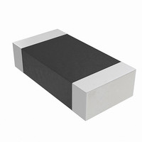
NTHS0603N10N1502JE
Description
THERMISTOR NTC 15K OHM 5% 0603
Manufacturer
Vishay
Series
NTHSr
Specifications of NTHS0603N10N1502JE
Resistance In Ohms @ 25°c
15K
Resistance Tolerance
±5%
B Value Tolerance
±3%
B25/75
3500K
Mounting Type
Surface Mount
Package / Case
0603 (1608 Metric)
Lead Free Status / RoHS Status
Lead free by exemption / RoHS Compliant
B0/50
-
B25/50
-
B25/85
-
B25/100
-
Operating Temperature
-
Power - Max
-
Lead Length
-
Lead Free Status / Rohs Status
Lead free / RoHS Compliant
Other names
541-1114-2
Available stocks
Company
Part Number
Manufacturer
Quantity
Price

Part Number:
NTHS0603N10N1502JE
Manufacturer:
VISHAY/威世
Quantity:
20 000


10.7
48
Sector Erase Command Sequence
Sector erase is a six bus cycle operation. The sector erase command sequence is initiated by writing two
unlock cycles, followed by a set-up command. Two additional unlock cycles are written, and are then followed
by the address of the sector to be erased, and the sector erase command.
Table 10.3 on page 53
The device does not require the system to preprogram prior to erase. The Embedded Erase algorithm
automatically programs and verifies the entire memory for an all zero data pattern prior to electrical erase.
The system is not required to provide any controls or timings during these operations.
After the command sequence is written, a sector erase time-out of 50 µs occurs. During the time-out period,
additional sector addresses and sector erase commands may be written. Loading the sector erase buffer may
be done in any sequence, and the number of sectors may be from one sector to all sectors. The time between
these additional cycles must be less than 50 µs, otherwise erasure may begin. Any sector erase address and
command following the exceeded time-out may or may not be accepted. It is recommended that processor
interrupts be disabled during this time to ensure all commands are accepted. The interrupts can be
re-enabled after the last Sector Erase command is written. Any command other than Sector Erase or
Erase Suspend during the time-out period resets the device to the read mode. Note that the Secured
Silicon Sector, autoselect, and CFI functions are unavailable when an erase operation is in progress.
The system must rewrite the command sequence and any additional addresses and commands.
The system can monitor DQ3 to determine if the sector erase timer has timed out (See the section on DQ3:
Sector Erase Timer.). The time-out begins from the rising edge of the final WE# pulse in the command
sequence.
When the Embedded Erase algorithm is complete, the device returns to reading array data and addresses
are no longer latched. The system can determine the status of the erase operation by reading DQ7, DQ6, or
DQ2 in the erasing sector. Refer to the Write Operation Status section for information on these status bits.
Once the sector erase operation begins, only the Erase Suspend command is valid. All other commands are
ignored. However, note that a hardware reset immediately terminates the erase operation. If that occurs, the
sector erase command sequence should be reinitiated once the device returns to reading array data, to
ensure data integrity.
Figure 10.4 on page 49
parameters, and
Figure 15.7 on page 69
shows the address and data requirements for the sector erase command sequence.
illustrates the algorithm for the erase operation. Refer to
S29GL-N MirrorBit
for timing diagrams.
D a t a
®
Flash Family
S h e e t
Table 10.1 on page 51
S29GL-N_01_12 October 29, 2008
Table 15.3 on page 67
and
for
Related parts for NTHS0603N10N1502JE
Image
Part Number
Description
Manufacturer
Datasheet
Request
R

Part Number:
Description:
357-036-542-201 CARDEDGE 36POS DL .156 BLK LOPRO
Manufacturer:
Vishay
Datasheet:
Part Number:
Description:
357-036-542-201 CARDEDGE 36POS DL .156 BLK LOPRO
Manufacturer:
Vishay
Datasheet:
Part Number:
Description:
357-036-542-201 CARDEDGE 36POS DL .156 BLK LOPRO
Manufacturer:
Vishay
Datasheet:
Part Number:
Description:
357-036-542-201 CARDEDGE 36POS DL .156 BLK LOPRO
Manufacturer:
Vishay
Datasheet:
Part Number:
Description:
357-036-542-201 CARDEDGE 36POS DL .156 BLK LOPRO
Manufacturer:
Vishay
Datasheet:
Part Number:
Description:
357-036-542-201 CARDEDGE 36POS DL .156 BLK LOPRO
Manufacturer:
Vishay
Datasheet:
Part Number:
Description:
357-036-542-201 CARDEDGE 36POS DL .156 BLK LOPRO
Manufacturer:
Vishay
Datasheet:
Part Number:
Description:
357-036-542-201 CARDEDGE 36POS DL .156 BLK LOPRO
Manufacturer:
Vishay
Datasheet:
Part Number:
Description:
357-036-542-201 CARDEDGE 36POS DL .156 BLK LOPRO
Manufacturer:
Vishay
Datasheet:
Part Number:
Description:
357-036-542-201 CARDEDGE 36POS DL .156 BLK LOPRO
Manufacturer:
Vishay
Datasheet:
Part Number:
Description:
357-036-542-201 CARDEDGE 36POS DL .156 BLK LOPRO
Manufacturer:
Vishay
Datasheet:
Part Number:
Description:
357-036-542-201 CARDEDGE 36POS DL .156 BLK LOPRO
Manufacturer:
Vishay
Datasheet:
Part Number:
Description:
357-036-542-201 CARDEDGE 36POS DL .156 BLK LOPRO
Manufacturer:
Vishay
Datasheet:
Part Number:
Description:
357-036-542-201 CARDEDGE 36POS DL .156 BLK LOPRO
Manufacturer:
Vishay
Datasheet:
Part Number:
Description:
357-036-542-201 CARDEDGE 36POS DL .156 BLK LOPRO
Manufacturer:
Vishay
Datasheet: