NTHS0603N10N1502JE Vishay, NTHS0603N10N1502JE Datasheet - Page 32
NTHS0603N10N1502JE
Manufacturer Part Number
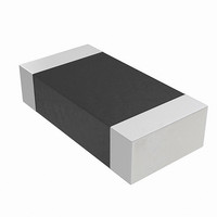
NTHS0603N10N1502JE
Description
THERMISTOR NTC 15K OHM 5% 0603
Manufacturer
Vishay
Series
NTHSr
Specifications of NTHS0603N10N1502JE
Resistance In Ohms @ 25°c
15K
Resistance Tolerance
±5%
B Value Tolerance
±3%
B25/75
3500K
Mounting Type
Surface Mount
Package / Case
0603 (1608 Metric)
Lead Free Status / RoHS Status
Lead free by exemption / RoHS Compliant
B0/50
-
B25/50
-
B25/85
-
B25/100
-
Operating Temperature
-
Power - Max
-
Lead Length
-
Lead Free Status / Rohs Status
Lead free / RoHS Compliant
Other names
541-1114-2
Available stocks
Company
Part Number
Manufacturer
Quantity
Price

Part Number:
NTHS0603N10N1502JE
Manufacturer:
VISHAY/威世
Quantity:
20 000


D a t a
S h e e t
Volatile. Individual PPB bits are set with a program command but must all be cleared as a group through an
erase command.
The PPB Lock Bit adds an additional level of protection. Once all PPB bits are programmed to the desired
settings, the PPB Lock Bit may be set to the “freeze state”. Setting the PPB Lock Bit to the “freeze state”
disables all program and erase commands to the Non-Volatile PPB bits. In effect, the PPB Lock Bit locks the
PPB bits into their current state. The only way to clear the PPB Lock Bit to the “unfreeze state” is to go
through a power cycle, or hardware reset. The Software Reset command does not clear the PPB Lock Bit to
the “unfreeze state”. System boot code can determine if any changes to the PPB bits are needed e.g. to allow
new system code to be downloaded. If no changes are needed then the boot code can set the PPB Lock Bit
to disable any further changes to the PPB bits during system operation.
The WP# write protect pin adds a final level of hardware protection. When this pin is low it is not possible to
change the contents of the WP# protected sectors. These sectors generally hold system boot code. So, the
WP# pin can prevent any changes to the boot code that could override the choices made while setting up
sector protection during system initialization.
It is possible to have sectors that have been persistently locked, and sectors that are left in the dynamic state.
The sectors in the dynamic state are all unprotected. If there is a need to protect some of them, a simple DYB
Set command sequence is all that is necessary. The DYB Set and DYB Clear commands for the dynamic
sectors switch the DYB bits to signify protected and unprotected, respectively. If there is a need to change the
status of the persistently locked sectors, a few more steps are required. First, the PPB Lock Bit must be
disabled to the “unfreeze state” by either putting the device through a power-cycle, or hardware reset. The
PPB bits can then be changed to reflect the desired settings. Setting the PPB Lock Bit once again to the
“freeze state” locks the PPB bits, and the device operates normally again.
To achieve the best protection, execute the PPB Lock Bit Set command early in the boot code, and protect
the boot code by holding WP# = V
.
IL
8.11.2
Persistent Protection Bit (PPB)
A single Persistent (non-volatile) Protection Bit is assigned to each sector. If a PPB is programmed to the
protected state through the “PPB Program” command, that sector is protected from program or erase
operations and is therefor read-only. If a PPB requires erasure, all of the sector PPB bits must first be erased
in parallel through the “All PPB Erase” command. The “All PPB Erase” command preprograms all PPB bits
prior to PPB erasing. All PPB bits erase in parallel, unlike programming where individual PPB bits are
programmable. The PPB bits are limited to the same number of cycles as a flash memory sector.
Programming the PPB bit requires the typical word programming time without utilizing the Write Buffer.
During a PPB bit programming and all PPB bit erasing sequence executions, the DQ6 Toggle Bit I toggles
until the programming of the PPB bit or erasing of all PPB bits has completed to indicate programming and
erasing status. Erasing all of the PPB bits at once requires typical sector erase time. During the erasing of all
PPB bits, the DQ3 Sector Erase Timer bit outputs a 1 to indicate the erasure of all PPB bits are in progress.
When the erasure of all PPB bits has completed, the DQ3 Sector Erase Timer bit outputs a 0 to indicate that
all PPB bits have been erased. Reading the PPB Status bit requires the initial access time of the device.
®
32
S29GL-N MirrorBit
Flash Family
S29GL-N_01_12 October 29, 2008
Related parts for NTHS0603N10N1502JE
Image
Part Number
Description
Manufacturer
Datasheet
Request
R

Part Number:
Description:
357-036-542-201 CARDEDGE 36POS DL .156 BLK LOPRO
Manufacturer:
Vishay
Datasheet:
Part Number:
Description:
357-036-542-201 CARDEDGE 36POS DL .156 BLK LOPRO
Manufacturer:
Vishay
Datasheet:
Part Number:
Description:
357-036-542-201 CARDEDGE 36POS DL .156 BLK LOPRO
Manufacturer:
Vishay
Datasheet:
Part Number:
Description:
357-036-542-201 CARDEDGE 36POS DL .156 BLK LOPRO
Manufacturer:
Vishay
Datasheet:
Part Number:
Description:
357-036-542-201 CARDEDGE 36POS DL .156 BLK LOPRO
Manufacturer:
Vishay
Datasheet:
Part Number:
Description:
357-036-542-201 CARDEDGE 36POS DL .156 BLK LOPRO
Manufacturer:
Vishay
Datasheet:
Part Number:
Description:
357-036-542-201 CARDEDGE 36POS DL .156 BLK LOPRO
Manufacturer:
Vishay
Datasheet:
Part Number:
Description:
357-036-542-201 CARDEDGE 36POS DL .156 BLK LOPRO
Manufacturer:
Vishay
Datasheet:
Part Number:
Description:
357-036-542-201 CARDEDGE 36POS DL .156 BLK LOPRO
Manufacturer:
Vishay
Datasheet:
Part Number:
Description:
357-036-542-201 CARDEDGE 36POS DL .156 BLK LOPRO
Manufacturer:
Vishay
Datasheet:
Part Number:
Description:
357-036-542-201 CARDEDGE 36POS DL .156 BLK LOPRO
Manufacturer:
Vishay
Datasheet:
Part Number:
Description:
357-036-542-201 CARDEDGE 36POS DL .156 BLK LOPRO
Manufacturer:
Vishay
Datasheet:
Part Number:
Description:
357-036-542-201 CARDEDGE 36POS DL .156 BLK LOPRO
Manufacturer:
Vishay
Datasheet:
Part Number:
Description:
357-036-542-201 CARDEDGE 36POS DL .156 BLK LOPRO
Manufacturer:
Vishay
Datasheet:
Part Number:
Description:
357-036-542-201 CARDEDGE 36POS DL .156 BLK LOPRO
Manufacturer:
Vishay
Datasheet: