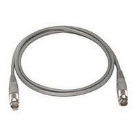
11730D AGILENT TECHNOLOGIES, 11730D Datasheet - Page 137

11730D
Manufacturer Part Number
11730D
Description
SENSOR CABLE, 50FT
Manufacturer
AGILENT TECHNOLOGIES
Datasheet
1.11730D.pdf
(234 pages)
Specifications of 11730D
Leaded Process Compatible
No
Peak Reflow Compatible (260 C)
No
Cable Length
50ft
Features
Reduces RFI Effect On Low Power Readings With Improved Shielding Design
Cable Assembly Type
Sensor
Cable Color
Gray
Rohs Compliant
No
For Use With
8480 & E-Series Power Sensors
Lead Free Status / RoHS Status
Contains lead / RoHS non-compliant
- Current page: 137 of 234
- Download datasheet (7Mb)
126
15
Switches
High Performance Matrix Switch (continued)
Driving the switch
DC power connection
• Connect pin 1 to supply ( +20 V DC to +32 V DC)
• Connect pin 15 to chassis ground to enable the electronic position-indicating circuitry and drive logic circuitry.
RF path selection
To connect any two RF ports, apply control signals to the corresponding drive pins as shown below:
Table 1. Agilent 87406B RF port drive pin control data
Using this table, select (close) the desired RF path by connecting ground (standard and Option 100) or applying TTL “High” (Option T24
or Option T00) to the corresponding “drive” pins.
Unselect (open) RF paths by disconnecting ground (standard and Option 100) or applying TTL “Low” (Option T24 or Option T00) to the
corresponding “drive” pins.
Example: Configure the RF path from port 2 to port 5
Using the data in Table 1, select pins 5 and 11 while ensuring no other pins are selected:
U = Ungrounded, G = Grounded, L = TTL “Low”, H = TTL “High”, X = Don’t care
* “Open All Ports” is not available with Option 100 and Option T00.
** “Open all RF Ports” feature is overridden by port selection.
Selected ports will be closed and unselected ports will be automatically opened by the internal logic circuits when new port selections
are made. After the RF port is switched and magnetically latched, the solenoid current is interrupted by the solid-state position sensing
circuitry. The drive voltage must be maintained to avoid RF path disconnection by the internal logic. For this reason, pulsed drive is NOT
recommended.
WARNING: DAMAGE TO SWITCH WILL OCCUR IF PIN 15 IS NOT GROUNDED
RF port
1
2
3
4
5
RF port
Drive pin
Standard, Option 100
Options T24, T00
6
3, 13
5, 13
7, 13
9, 13
11, 13
1
3
U
L
2
5
G
H
5
3, 11
5, 11
7, 11
9, 11
3
7
U
L
4
3, 9
5, 9
7, 9
4
9
U
L
5
11
G
H
3
3, 7
5, 7
6
13
U
L
2
3, 5
Open All*
16
X**
X**
Related parts for 11730D
Image
Part Number
Description
Manufacturer
Datasheet
Request
R

Part Number:
Description:
Agilent Tachyon DX4+ (HPFC-5700) Dual-Channel 4-Gb Fibre Channel Controller With The Data Integrity Field (DIF) Feature
Manufacturer:
Agilent Technologies, Inc.

Part Number:
Description:
Manufacturer:
Agilent Technologies, Inc.
Datasheet:

Part Number:
Description:
Manufacturer:
Agilent Technologies, Inc.
Datasheet:

Part Number:
Description:
Manufacturer:
Agilent Technologies, Inc.
Datasheet:

Part Number:
Description:
Manufacturer:
Agilent Technologies, Inc.
Datasheet:

Part Number:
Description:
Manufacturer:
Agilent Technologies, Inc.
Datasheet:

Part Number:
Description:
Manufacturer:
Agilent Technologies, Inc.
Datasheet:

Part Number:
Description:
Manufacturer:
Agilent Technologies, Inc.
Datasheet:

Part Number:
Description:
Manufacturer:
Agilent Technologies, Inc.
Datasheet:

Part Number:
Description:
Manufacturer:
Agilent Technologies, Inc.
Datasheet:

Part Number:
Description:
Manufacturer:
Agilent Technologies, Inc.
Datasheet:

Part Number:
Description:
Manufacturer:
Agilent Technologies, Inc.
Datasheet:

Part Number:
Description:
1.0625 GBd Fibre Channel 10x10 mm QFP Transceiver Chip (Recommend HDMP-1636A for new designs)
Manufacturer:
Agilent Technologies, Inc.
Datasheet:

Part Number:
Description:
Manufacturer:
Agilent Technologies, Inc.
Datasheet:

Part Number:
Description:
1.0625-2.125 GBd Serdes Circuits: SSTL_2
Manufacturer:
Agilent Technologies, Inc.
Datasheet:


