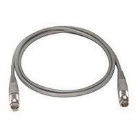
11730D AGILENT TECHNOLOGIES, 11730D Datasheet - Page 43

11730D
Manufacturer Part Number
11730D
Description
SENSOR CABLE, 50FT
Manufacturer
AGILENT TECHNOLOGIES
Datasheet
1.11730D.pdf
(234 pages)
Specifications of 11730D
Leaded Process Compatible
No
Peak Reflow Compatible (260 C)
No
Cable Length
50ft
Features
Reduces RFI Effect On Low Power Readings With Improved Shielding Design
Cable Assembly Type
Sensor
Cable Color
Gray
Rohs Compliant
No
For Use With
8480 & E-Series Power Sensors
Lead Free Status / RoHS Status
Contains lead / RoHS non-compliant
- Current page: 43 of 234
- Download datasheet (7Mb)
32
5
Attenuators
Attenuators
Applications
Agilent fixed and step attenuators find use in a wide variety of
applications for signal conditioning and level control.
• Reducing signal levels
• Matching impedances of sources and loads
• Measuring gain or loss of a two-port device
Key specifications
• SWR
• Accuracy
• Repeatability
• Life
SWR
Most attenuators use some form of distributed thin-film
attenuating element, designed to operate over multi-octave
ranges and for low SWR match at input and output. The SWR
characteristic is controlled with careful design of the element
as well as the transition from RF connector to the element’s
planar geometry.
When an attenuator is inserted into a test network, the interaction
of its SWR and the network SWR results in frequency-varying
mismatch, which degrades the accuracy of the measurement. The
amount of variation often exceeds the flatness specification of the
attenuator. As an example, if at a given frequency, a 3 dB
attenuator with SWR of 1.22 at each port is inserted into a
microwave network that has a source and load SWR of 1.35, the
variation from the expected 3 dB change could be as great as
±0.5 dB. This change is due to SWR alone and points out the
importance of the SWR specification in a precision attenuator.
Accuracy
The accuracy of an attenuator directly affects the uncertainty of
the measurement where the attenuator is used. In many
measurement and metrology applications, attenuators are the
basic standard against which other components and instruments
are calibrated.
Agilent attenuator accuracy specifications always include the
effect of frequency response. And, Agilent attenuators use
“edgeline” coaxial structure technology to achieve low-insertion
loss and SWR resulting in better accuracy.
Agilent attenuators achieve flat-frequency response and high
accuracy through the use of thin-film attenuator cards. These
cards are composed of high-stability tantalum nitride resistive film,
deposited on sapphire or alumina substrates. Advanced design
and state-of-the-art processes in the deposition stages allow
precise control of the geometry and thus the attenuation value.
The result is very flat frequency response and greater accuracy.
Ultimate specified accuracy of RF/microwave attenuators is
limited by the accuracy to which National Institute of Standards
and Technology (NIST) can measure, plus the uncertainty of the
measurement transfer process which calibrates the production test
equipment. See Figure 1, on the next page, for an accuracy
traceability example. At Agilent, performance to specifications is
verified by fully testing each attenuator with an ATE system
including an automatic network analyzer (ANA). In turn, the ANA
is periodically calibrated using standards traceable to NIST.
Each published specification has been established using a
“specification budget” process. This process provides for
“guardbands” to account for transfer uncertainties between NIST,
Agilent Metrology Labs, and the Agilent production test systems.
Figure 2, on the next page, shows how the specification budget is
allocated.
Related parts for 11730D
Image
Part Number
Description
Manufacturer
Datasheet
Request
R

Part Number:
Description:
Agilent Tachyon DX4+ (HPFC-5700) Dual-Channel 4-Gb Fibre Channel Controller With The Data Integrity Field (DIF) Feature
Manufacturer:
Agilent Technologies, Inc.

Part Number:
Description:
Manufacturer:
Agilent Technologies, Inc.
Datasheet:

Part Number:
Description:
Manufacturer:
Agilent Technologies, Inc.
Datasheet:

Part Number:
Description:
Manufacturer:
Agilent Technologies, Inc.
Datasheet:

Part Number:
Description:
Manufacturer:
Agilent Technologies, Inc.
Datasheet:

Part Number:
Description:
Manufacturer:
Agilent Technologies, Inc.
Datasheet:

Part Number:
Description:
Manufacturer:
Agilent Technologies, Inc.
Datasheet:

Part Number:
Description:
Manufacturer:
Agilent Technologies, Inc.
Datasheet:

Part Number:
Description:
Manufacturer:
Agilent Technologies, Inc.
Datasheet:

Part Number:
Description:
Manufacturer:
Agilent Technologies, Inc.
Datasheet:

Part Number:
Description:
Manufacturer:
Agilent Technologies, Inc.
Datasheet:

Part Number:
Description:
Manufacturer:
Agilent Technologies, Inc.
Datasheet:

Part Number:
Description:
1.0625 GBd Fibre Channel 10x10 mm QFP Transceiver Chip (Recommend HDMP-1636A for new designs)
Manufacturer:
Agilent Technologies, Inc.
Datasheet:

Part Number:
Description:
Manufacturer:
Agilent Technologies, Inc.
Datasheet:

Part Number:
Description:
1.0625-2.125 GBd Serdes Circuits: SSTL_2
Manufacturer:
Agilent Technologies, Inc.
Datasheet:


