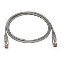
11730D AGILENT TECHNOLOGIES, 11730D Datasheet - Page 65

11730D
Manufacturer Part Number
11730D
Description
SENSOR CABLE, 50FT
Manufacturer
AGILENT TECHNOLOGIES
Datasheet
1.11730D.pdf
(234 pages)
Specifications of 11730D
Leaded Process Compatible
No
Peak Reflow Compatible (260 C)
No
Cable Length
50ft
Features
Reduces RFI Effect On Low Power Readings With Improved Shielding Design
Cable Assembly Type
Sensor
Cable Color
Gray
Rohs Compliant
No
For Use With
8480 & E-Series Power Sensors
Lead Free Status / RoHS Status
Contains lead / RoHS non-compliant
- Current page: 65 of 234
- Download datasheet (7Mb)
54
8
Detectors
Detectors (continued)
Figure 4 shows the typical equivalent
circuit of a test detector, and can help in
devising the external terminations and
cables to connect to an oscilloscope or
other instrument. The following equation
gives the approximate rise time for
different conditions of load resistance and
capacitance. Note that rise time can be
improved (lowered) with a termination of
less than 50 Ω. This rise time improvement
comes at the expense of lower pulse
output voltage. The lower voltage can
be overcome with the gain of a high
performance oscilloscope.
Broadband match (SWR)
In many applications, the match (SWR) of
the detector is of prime importance in
minimizing the uncertainty of power
measurements. If the input of the detector
is not well matched to the source, simple
and multiple mismatch errors will result,
reducing the accuracy of the measurement.
Figure 5 represents the mismatch error
introduced by multiple reflections caused
by a mismatch between the detector and
the source. For a detector SWR of 2.0 and
source SWR of 2.0, the uncertainty is
±1.0 dB. For the LBSD and PDBD models,
the integration of the diode with the 50 Ω
matching resistor results in an excellent
broadband match. Both LBSD and PDBD
detectors utilize thin-film technology which
yields a precision matching circuit that
minimizes stray reactance and yields very
good performance. Figure 6 displays typical
SWR for the Agilent 8473B,C LBSD
detector and the Agilent 8473D PDBD
detector.
1.0
T r (10% to 90%) =
Where
R
R
Figure 5. Mismatch error from detector and source mismatch.
Figure 4. Detector model.
Figure 6. Typical SWR of detectors.
L
V
RF in
= Load impedance
2.1
2.0
1.9
1.8
1.7
1.6
1.5
1.4
1.3
1.2
1.1
1.0
= Video impedance
2 4 6 8 10 12 14 16 18 20 22 24 26 28 30 32
50 Ω
1.2
Typical Agilent 8473B,C
PDB
Detector SWR
2.0 Source SWR
Equivalent diode
1.4
R
2.2 * R
V,
Typical Agilent 8473D
Frequency (GHz)
V
impedance
Diode video
Schottky
L
1.5 Source SWR
R
* R
1.6
L
C
C
V
+R
L
b
* (C
= Load capacitance
= Bypass capacitance
V
L
+C
1.8
b
)
C b , RF bypass
=
capacitor
Video out
2.0
0.35
BW
Typical values:
R
C
1
Determined by
Measuring equipment Detector
Measuring equipment Detector
@ 25 °C and P in <–20 dBm.
Extremely sensitive to power
and temperature.
v
b
(diode video impedance) = 1.5 kΩ
(RF bypass capacitor) = 27 pF nom.
1
Related parts for 11730D
Image
Part Number
Description
Manufacturer
Datasheet
Request
R

Part Number:
Description:
Agilent Tachyon DX4+ (HPFC-5700) Dual-Channel 4-Gb Fibre Channel Controller With The Data Integrity Field (DIF) Feature
Manufacturer:
Agilent Technologies, Inc.

Part Number:
Description:
Manufacturer:
Agilent Technologies, Inc.
Datasheet:

Part Number:
Description:
Manufacturer:
Agilent Technologies, Inc.
Datasheet:

Part Number:
Description:
Manufacturer:
Agilent Technologies, Inc.
Datasheet:

Part Number:
Description:
Manufacturer:
Agilent Technologies, Inc.
Datasheet:

Part Number:
Description:
Manufacturer:
Agilent Technologies, Inc.
Datasheet:

Part Number:
Description:
Manufacturer:
Agilent Technologies, Inc.
Datasheet:

Part Number:
Description:
Manufacturer:
Agilent Technologies, Inc.
Datasheet:

Part Number:
Description:
Manufacturer:
Agilent Technologies, Inc.
Datasheet:

Part Number:
Description:
Manufacturer:
Agilent Technologies, Inc.
Datasheet:

Part Number:
Description:
Manufacturer:
Agilent Technologies, Inc.
Datasheet:

Part Number:
Description:
Manufacturer:
Agilent Technologies, Inc.
Datasheet:

Part Number:
Description:
1.0625 GBd Fibre Channel 10x10 mm QFP Transceiver Chip (Recommend HDMP-1636A for new designs)
Manufacturer:
Agilent Technologies, Inc.
Datasheet:

Part Number:
Description:
Manufacturer:
Agilent Technologies, Inc.
Datasheet:

Part Number:
Description:
1.0625-2.125 GBd Serdes Circuits: SSTL_2
Manufacturer:
Agilent Technologies, Inc.
Datasheet:


