PAXTM000 Red Lion Controls, PAXTM000 Datasheet - Page 20
PAXTM000
Manufacturer Part Number
PAXTM000
Description
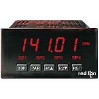
Digital Multifunction Timer
Manufacturer
Red Lion Controls
Type
Timerr
Datasheet
1.PAXTM000.pdf
(28 pages)
Specifications of PAXTM000
Time Range
0.001sec To 1hr
Power Consumption
18VA
Supply Voltage Ac, Min
85V
Signal Input Type
Pulse
Supply Voltage Max
250VAC
Time Range Max
999999h
Character Size
0.56"
Accuracy
±0.01% %
Connection Type
Cage-Clamp
Cut Out, Panel
3.62×1.77 "
Digit Height
0.48
Dimensions
4.2"L×3.8"W×1.95"H
Display Digit Height
0.56 "
Display Resolution
0.001 Sec. (Minimum Digit), 1 hr. (Single Digit)
Display Type
LED
Function
Timer
Humidity
0 to 85% (Max.) RH
Isolation Voltage
2300 V (RMS)
Length, Stripping
0.3 in. Wire
Memory Type
Non-Volatile EEPROM
Number Of Digits
5
Power, Rating
18 VA
Primary Type
Electronic
Range, Measurement
0 to 999999
Special Features
programmable
Standards
cULus Listed, CSA Certified
Temperature, Operating
0 to +50 °C
Termination
Cage Clamp
Torque
4.5 in.-lbs
Voltage, Range
85 to 250 VAC
Voltage, Supply
85 to 250 VAC
Four Separate Displays
Timer, Counter, Real-Time Clock and Date
Display Font Color
Red
No. Of Digits / Alpha
6
Supply Voltage Ac, Max
250V
Rohs Compliant
Yes
Lead Free Status / RoHS Status
Lead free / RoHS Compliant


Parameters. These parameters are used to match the serial settings of the PAX
with those of the host computer or other serial device, such as a terminal or
printer. This programming module can only be accessed if an RS232 or RS485
Serial Communications card is installed.
required for communicating with the PAX. In order to establish serial
communications, the user must have host software that can send and receive
ASCII characters. Red Lion’s Crimson
the PAX. (See ordering information.) For serial hardware and wiring details,
refer to section 4.5 Serial Communication Wiring.
RS232 and RS485 serial communications plug-in cards. Discard the separate
bulletin when using those serial plug-in cards with the PAXTM/CK. Also, this
section does NOT apply to the DeviceNet, Modbus, or Profibus-DP
communication cards. For details on the operation of the Fieldbus cards, refer
to the bulletin shipped with each card.
serial link. Normally, the baud rate is set to the highest value at which all the
serial equipment are capable of transmitting and receiving data.
other serial communications equipment on the serial link.
data word length. Set the parity bit to match that of the other serial
communications equipment on the serial link. The meter ignores parity when
receiving data and sets the parity bit for outgoing data. If parity is set to
additional stop bit is used to force the frame size to 10 bits.
needed and a value of zero can be used. With multiple meters (RS485
applications), a unique 2 digit address number must be assigned to each meter.
clock master. See Serial Real-time Clock Master Adressing.
6.7 MODULE 7 - S
This module can only be accessed if a Serial Communications Card is installed.
* Only appears if the Real-Time Clock Card is installed.
Module 7 is the programming module for the Serial Communications
This section also includes an explanation of the commands and formatting
This section of the PAXTM/CK bulletin replaces the bulletin shipped with the
Set the baud rate to match the other serial communications equipment on the
Select either 7- or 8-bit data word lengths. Set the word length to match the
This parameter only appears when the Data Bits parameter is set to a 7-bit
Enter the serial meter (node) address. With a single meter, an address is not
Addresses 98 and 99 are reserved to configure a unit as a serial real-time
METER ADDRESS
to
BAUD RATE
PARITY BIT
DATA BITS
software can be used for configuring
ERIAL
C
PARAMETER MENU
OMMUNICATIONS
, an
20
in response to a Transmit Value (T) command or a Block Print Request (P)
command. Select
address, mnemonics, and parameter data. Select
transmissions, consisting of the parameter data only. This setting affects all the
parameters selected in the PRINT OPTIONS. (Note: If the meter address is 00,
the address will not be sent during a Full transmission.)
PAXCK: REAL-TIME CLOCK PRINT FORMATTING
values transmitted from the meter in response to a Transmit Value (T) command
or a Block Print Request (P) command. This parameter appears only when a
Real-Time Clock plug-in option card is installed.
Date Display Formats programmed in Module 8. The Day of Week value is sent
as a character string.
This selection allows the RTC values to be recognized by the Red Lion HMI
products. RTC Time/Date units are separated by a “.”. The Day is sent as a
single number as shown below.
Request. A Print Request is sometimes referred to as a block print because more
than one parameter can be sent to a printer or computer as a block.
in the block print. All parameters entered as
transmitted during a block print. Parameters entered as
*
These values are plug-in card dependent.
SpNtOF
StrStp
This parameter determines the formatting of data transmitted from the meter
This parameter determines the formatting of the Real-Time Clock (RTC)
When
When
This parameter selects the meter values transmitted in response to a Print
Selecting
DISPLAY
t-dsp
C-dSP
rtC-d
rtC-t
TIME - Hours (24-Hr. format), Minutes, Seconds (HHMMSS)
DATE - Month, Day, Year (mmddyy)
DAY - 1 = Sunday thru 7 = Saturday
SPNt
is selected, the meter sends the RTC values as numeric data only.
is selected, RTC values are formatted as per the RTC Time and
PARAMETER
Timer
Cycle Counter
RTC Date*
RTC Time*
Setpoint Values*
Setpoint Off/Time-Out Values*
Timer/Cnt Start & Stop Values
displays a sublist for choosing the meter parameters to appear
for a Full print transmission, which consists of the meter
ABBREVIATED PRINTING
P
ARAMETERS
PRINT OPTIONS
FACTORY
yES
NO
NO
NO
NO
NO
NO
(
in the sublist will be
for abbreviated print
will not be sent.
MNEMONIC
TMR
CNT
DAT
TIM
SP1 SP2 SP3 SP4
SO1 SO2 SO3 SO4
TST TSP CST CSP
)
Related parts for PAXTM000
Image
Part Number
Description
Manufacturer
Datasheet
Request
R

Part Number:
Description:
Counter
Manufacturer:
Red Lion Controls
Datasheet:
Part Number:
Description:
Miniature Length Sensor
Manufacturer:
Red Lion Controls
Datasheet:
Part Number:
Description:
Model Lsc - Single Channel Output Length Sensor
Manufacturer:
Red Lion Controls
Datasheet: