PAXTM000 Red Lion Controls, PAXTM000 Datasheet - Page 7
PAXTM000
Manufacturer Part Number
PAXTM000
Description
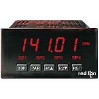
Digital Multifunction Timer
Manufacturer
Red Lion Controls
Type
Timerr
Datasheet
1.PAXTM000.pdf
(28 pages)
Specifications of PAXTM000
Time Range
0.001sec To 1hr
Power Consumption
18VA
Supply Voltage Ac, Min
85V
Signal Input Type
Pulse
Supply Voltage Max
250VAC
Time Range Max
999999h
Character Size
0.56"
Accuracy
±0.01% %
Connection Type
Cage-Clamp
Cut Out, Panel
3.62×1.77 "
Digit Height
0.48
Dimensions
4.2"L×3.8"W×1.95"H
Display Digit Height
0.56 "
Display Resolution
0.001 Sec. (Minimum Digit), 1 hr. (Single Digit)
Display Type
LED
Function
Timer
Humidity
0 to 85% (Max.) RH
Isolation Voltage
2300 V (RMS)
Length, Stripping
0.3 in. Wire
Memory Type
Non-Volatile EEPROM
Number Of Digits
5
Power, Rating
18 VA
Primary Type
Electronic
Range, Measurement
0 to 999999
Special Features
programmable
Standards
cULus Listed, CSA Certified
Temperature, Operating
0 to +50 °C
Termination
Cage Clamp
Torque
4.5 in.-lbs
Voltage, Range
85 to 250 VAC
Voltage, Supply
85 to 250 VAC
Four Separate Displays
Timer, Counter, Real-Time Clock and Date
Display Font Color
Red
No. Of Digits / Alpha
6
Supply Voltage Ac, Max
250V
Rohs Compliant
Yes
Lead Free Status / RoHS Status
Lead free / RoHS Compliant


4.1 POWER WIRING
4.3 USER INPUT WIRING
count, in module 4, the count input should be wired between terminals 7 & 10.
Sinking Logic
Terminals 7-9
Terminal 10
4.2 TIMER INPUT WIRING
The user inputs of the meter are internally
pulled up to +12 V with 22 KΩ resistance.
The input is active when it is pulled low
(<0 .9 V).
Before connecting the wires, the Timer Input logic jumper should be verified for proper position. When the user input is configured for cycle
AC Power
Terminal 1: VAC
Terminal 2: VAC
Before connecting the wires, the Timer Input logic jumper should be verified for proper position.
Two Wire Proximity, Current Source
CAUTION: Timer Input common is NOT isolated from User Input common. In order to preserve the safety of the meter application, the timer input
common must be suitably isolated from hazardous live earth referenced voltage; or input common must be at protective earth ground potential. If not,
hazardous voltage may be present at the User Inputs and User Input Common terminals. Appropriate considerations must then be given to the potential
of the User Input Common with respect to earth ground; and the common of the isolated plug-in cards with respect to input common.
}
Switch or Isolated Transistor; Current Sink
Connect external switching device between the
appropriate User Input terminal and User Comm.
Interfacing With TTL
DC Power
Terminal 1: +VDC
Terminal 2: -VDC
Current Sinking Output
7
Sourcing Logic
Terminals 7-9:
Terminal 10:
The user inputs of the meter are internally
pulled down to 0 V with 22 KΩ resistance.
The input is active when a voltage greater
than 3.6 VDC is applied.
+ VDC through external switching device
-VDC through external switching device
Switch or Isolated Transistor; Current Source
Emitter Follower; Current Source
Current Sourcing Output
Related parts for PAXTM000
Image
Part Number
Description
Manufacturer
Datasheet
Request
R

Part Number:
Description:
Counter
Manufacturer:
Red Lion Controls
Datasheet:
Part Number:
Description:
Miniature Length Sensor
Manufacturer:
Red Lion Controls
Datasheet:
Part Number:
Description:
Model Lsc - Single Channel Output Length Sensor
Manufacturer:
Red Lion Controls
Datasheet: