PAXTM000 Red Lion Controls, PAXTM000 Datasheet - Page 5
PAXTM000
Manufacturer Part Number
PAXTM000
Description
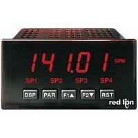
Digital Multifunction Timer
Manufacturer
Red Lion Controls
Type
Timerr
Datasheet
1.PAXTM000.pdf
(28 pages)
Specifications of PAXTM000
Time Range
0.001sec To 1hr
Power Consumption
18VA
Supply Voltage Ac, Min
85V
Signal Input Type
Pulse
Supply Voltage Max
250VAC
Time Range Max
999999h
Character Size
0.56"
Accuracy
±0.01% %
Connection Type
Cage-Clamp
Cut Out, Panel
3.62×1.77 "
Digit Height
0.48
Dimensions
4.2"L×3.8"W×1.95"H
Display Digit Height
0.56 "
Display Resolution
0.001 Sec. (Minimum Digit), 1 hr. (Single Digit)
Display Type
LED
Function
Timer
Humidity
0 to 85% (Max.) RH
Isolation Voltage
2300 V (RMS)
Length, Stripping
0.3 in. Wire
Memory Type
Non-Volatile EEPROM
Number Of Digits
5
Power, Rating
18 VA
Primary Type
Electronic
Range, Measurement
0 to 999999
Special Features
programmable
Standards
cULus Listed, CSA Certified
Temperature, Operating
0 to +50 °C
Termination
Cage Clamp
Torque
4.5 in.-lbs
Voltage, Range
85 to 250 VAC
Voltage, Supply
85 to 250 VAC
Four Separate Displays
Timer, Counter, Real-Time Clock and Date
Display Font Color
Red
No. Of Digits / Alpha
6
Supply Voltage Ac, Max
250V
Rohs Compliant
Yes
Lead Free Status / RoHS Status
Lead free / RoHS Compliant


squeezing and pulling back on the side rear finger tabs. This should lower the
latch below the case slot (which is located just in front of the finger tabs). It is
recommended to release the latch on one side, then start the other side latch.
1.0 I
Installation
installed. The meter is intended to be mounted into an enclosed panel. Prepare
the panel cutout to the dimensions shown. Remove the panel latch from the
2.0 S
To access the jumpers, remove the meter base from the meter case by firmly
The meter meets NEMA 4X/IP65 requirements for indoor use when properly
Warning: Exposed line voltage exists on the circuit boards. Remove
Main
Circuit
Board
all power to the meter and load circuits before accessing inside of
the meter.
JUMPER
TIMER
INPUT
NSTALLING THE
ETTING THE
SRC
SNK
SRC
meter. Slide the panel gasket over the
SNK
rear of the meter to the back of the
JUMPER
INPUT
USER
bezel. The meter should be
installed fully assembled.
Insert the meter into the
panel cutout.
J
UMPERS
M
ETER
5
meter so that the tabs of the panel latch engage in the slots on the case. The
panel latch should be engaged in the farthest forward slot possible. To achieve
a proper seal, tighten the latch screws evenly until the meter is snug in the panel
(Torque to approximately 7 in-lbs [79N-cm]). Do not over-tighten the screws.
Installation Environment
temperature and provides good air circulation. Placing the meter near devices
that generate excessive heat should be avoided.
Do NOT use solvents. Continuous exposure to direct sunlight may accelerate
the aging process of the bezel.
keypad of the meter.
Timer Input Logic Jumper
position to match the input being used.
User Input Logic Jumper
not used, it is not necessary to check or move this jumper.
While holding the meter in place, push the panel latch over the rear of the
The meter should be installed in a location that does not exceed the operating
The bezel should only be cleaned with a soft cloth and neutral soap product.
Do not use tools of any kind (screwdrivers, pens, pencils, etc.) to operate the
One jumper is used for the logic state of both timer inputs. Select the proper
One jumper is used for the logic state of all user inputs. If the user inputs are
JUMPER SELECTIONS
The
indicates factory setting.
PANEL CUT-OUT
Related parts for PAXTM000
Image
Part Number
Description
Manufacturer
Datasheet
Request
R

Part Number:
Description:
Counter
Manufacturer:
Red Lion Controls
Datasheet:
Part Number:
Description:
Miniature Length Sensor
Manufacturer:
Red Lion Controls
Datasheet:
Part Number:
Description:
Model Lsc - Single Channel Output Length Sensor
Manufacturer:
Red Lion Controls
Datasheet: