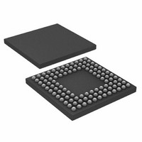
ADUC7121BBCZ-RL Analog Devices Inc, ADUC7121BBCZ-RL Datasheet - Page 64

ADUC7121BBCZ-RL
Manufacturer Part Number
ADUC7121BBCZ-RL
Description
PRECISION ANALOG MCU I.C
Manufacturer
Analog Devices Inc
Series
MicroConverter® ADuC7xxxr
Datasheet
1.ADUC7121BBCZ.pdf
(96 pages)
Specifications of ADUC7121BBCZ-RL
Core Processor
ARM7
Core Size
16/32-Bit
Speed
41.78MHz
Connectivity
I²C, SPI, UART/USART
Peripherals
POR, PWM, WDT
Number Of I /o
32
Program Memory Size
126KB (63K x 16)
Program Memory Type
FLASH
Ram Size
8K x 8
Voltage - Supply (vcc/vdd)
3 V ~ 3.6 V
Data Converters
A/D 9x12b, D/A 4x12b
Oscillator Type
Internal
Operating Temperature
-10°C ~ 95°C
Package / Case
108-LFBGA, CSPBGA
Lead Free Status / RoHS Status
Lead free / RoHS Compliant
Eeprom Size
-
Lead Free Status / RoHS Status
Lead free / RoHS Compliant
Other names
ADUC7121BBCZ-RL
ADUC7121BBCZ-RLTR
ADUC7121BBCZ-RLTR
Available stocks
Company
Part Number
Manufacturer
Quantity
Price
Company:
Part Number:
ADUC7121BBCZ-RL
Manufacturer:
Analog Devices Inc
Quantity:
10 000
ADuC7121
•
I
The I
I
I
This 16-bit MMR configures I
Name:
Address:
Default value:
Access:
Table 87. I2CxMCTL MMR Bit Designations
Bit
15:9
8
7
6
5
4
3
2
1
0
2
2
2
C Master Registers
C REGISTERS
C Master Control Register
I2CxADR0[0] is the read/ write bit.
2
C peripheral interfaces consists of a number of MMRs. These are described in the following section.
Name
I2CMCENI
I2CNACKENI
I2CALENI
I2CMTENI
I2CMRENI
I2CMSEN
I2CILEN
I2CBD
I2CMEN
I2C0MCTL, I2C1MCTL
0xFFFF0880, 0xFFFF0900
0x0000, 0x0000
Read/write
Description
Reserved. These bits are reserved; do not write to these bits.
I
Set this bit to enable an interrupt on detecting a stop condition on the I
Clear this interrupt source.
I
Set this bit to enable interrupts when the I
Clear this interrupt source.
I
Set this bit to enable interrupts when the I
Clear this interrupt source.
I
Set this bit to enable interrupts when the I
Clear this interrupt source.
I
Set this bit to enable interrupts when the I
Cleared by the user to disable interrupts when the I
I
Set this bit to 1 to enable clock stretching. When SCL is low, setting this bit forces the device to hold SCL low until
I2CMSEN is cleared. If SCL is high, setting this bit forces the device to hold SCL low after the next falling edge.
Clear this bit to disable clock stretching.
I
Set this bit to enable loopback test mode. In this mode, the SCL and SDA signals are connected internally to their
respective input signals.
Cleared by the user to disable loopback mode.
I
Set this bit to allow the device to compete for control of the bus even if another device is currently driving a start
condition.
Clear this bit to back off until the I
I
Set by the user to enable I
Clear this bit to disable I
2
2
2
2
2
2
2
2
2
C transmission complete interrupt enable bit.
C no acknowledge received interrupt enable bit.
C arbitration lost interrupt enable bit.
C transmit interrupt enable bit.
C receive interrupt enable bit.
C master SCL stretch enable bit.
C internal loopback enable.
C master back off disable bit.
C master enable bit.
2
C peripheral in master mode.
2
C master mode.
2
C master mode.
2
C bus becomes free.
Rev. 0 | Page 64 of 96
2
2
2
2
C master receives a no acknowledge.
C master has been unsuccessful in gaining control of the I
C master has transmitted a byte.
C master receives data.
2
C master is receiving data.
2
C bus.
2
C bus.


