FGA30N120FTDTU Fairchild Semiconductor, FGA30N120FTDTU Datasheet - Page 2
FGA30N120FTDTU
Manufacturer Part Number
FGA30N120FTDTU
Description
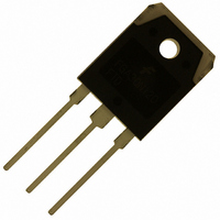
IGBT 30A 1200V TRENCH TO-3P
Manufacturer
Fairchild Semiconductor
Datasheet
1.FGA30N120FTDTU.pdf
(9 pages)
Specifications of FGA30N120FTDTU
Igbt Type
Trench and Field Stop
Voltage - Collector Emitter Breakdown (max)
1200V
Vce(on) (max) @ Vge, Ic
2V @ 15V, 30A
Current - Collector (ic) (max)
60A
Power - Max
339W
Input Type
Standard
Mounting Type
Through Hole
Package / Case
TO-3P
Channel Type
N
Configuration
Single
Collector-emitter Voltage
1.2kV
Collector Current (dc) (max)
60A
Gate To Emitter Voltage (max)
±25V
Package Type
TO-3PN
Pin Count
3 +Tab
Mounting
Through Hole
Operating Temperature (max)
150C
Operating Temperature Classification
Military
Collector- Emitter Voltage Vceo Max
1200 V
Collector-emitter Saturation Voltage
2 V
Maximum Gate Emitter Voltage
+/- 25 V
Continuous Collector Current At 25 C
30 A
Power Dissipation
339 W
Maximum Operating Temperature
+ 150 C
Continuous Collector Current Ic Max
60 A
Minimum Operating Temperature
- 55 C
Mounting Style
Through Hole
Lead Free Status / RoHS Status
Lead free / RoHS Compliant
Available stocks
Company
Part Number
Manufacturer
Quantity
Price
Company:

Part Number:
FGA30N120FTDTU
Manufacturer:
ALLEGRO
Quantity:
1 001


FGH30N120FTD
Package Marking and Ordering Information
Electrical Characteristics of the IGBT
Off Characteristics
BV
I
I
On Characteristics
V
V
Dynamic Characteristics
C
C
C
Switching Characteristics
t
t
t
t
E
E
E
t
t
t
t
E
E
E
Q
Q
Q
Device Marking
Symbol
CES
GES
d(on)
r
d(off)
f
d(on)
r
d(off)
f
GE(th)
CE(sat)
on
off
ts
on
off
ts
ies
oes
res
g
ge
gc
FGA30N120FTD
CES
For Fairchild’s definition of “green” Eco Status, please visit: http://www.fairchildsemi.com/company/green/rohs_green.html.
Rev. A
Collector to Emitter Breakdown Voltage V
Collector Cut-Off Current
G-E Leakage Current
G-E Threshold Voltage
Collector to Emitter Saturation Voltage
Input Capacitance
Output Capacitance
Reverse Transfer Capacitance
Turn-On Delay Time
Rise Time
Turn-Off Delay Time
Fall Time
Turn-On Switching Loss
Turn-Off Switching Loss
Total Switching Loss
Turn-On Delay Time
Rise Time
Turn-Off Delay Time
Fall Time
Turn-On Switching Loss
Turn-Off Switching Loss
Total Switching Loss
Total Gate Charge
Gate to Emitter Charge
Gate to Collector Charge
FGA30N120FTDTU
Parameter
Device
Package
TO-3PN
V
V
I
I
I
T
V
f = 1MHz
V
R
Resistive Load, T
V
R
Resistive Load, T
V
V
C
C
C
C
GE
CE
GE
CE
CC
CC
CE
GE
G
G
= 30A
= 30A
= 30mA, V
= 125
= 10Ω, V
= 10Ω, V
= 30V
= V
= 600V, I
= 0V, I
= V
= 600V, I
= 600V, I
= 15V
Test Conditions
T
C
CES
GES
,
,
o
= 25°C unless otherwise noted
V
V
C
,
GE
GE
2
C
V
, V
, V
GE
GE
GE
= 250µA
CE
C
C
C
= 15V
= 15V,
GE
CE
= 30A,
= 15V,
= 30A,
= 15V,
= 30A,
= 0V,
= V
C
C
= 0V
= 0V
Eco Status
= 25
= 125
GE
RoHS
o
C
o
C
Min.
1200
Packaging
3.5
-
-
-
-
-
-
-
-
-
-
-
-
-
-
-
-
-
-
-
-
-
-
-
-
Type
Tube
Typ.
5140
0.54
1.16
1.70
0.74
1.63
2.37
150
101
198
259
127
364
208
211
1.6
2.0
95
31
40
41
97
6
-
-
-
Max.
Qty per Tube
±250
1.51
7.5
1
2
-
-
-
-
-
-
-
-
-
-
-
-
-
-
-
-
-
-
-
-
-
www.fairchildsemi.com
30ea
Units
mA
nA
mJ
mJ
mJ
mJ
mJ
mJ
nC
nC
nC
pF
pF
pF
ns
ns
ns
ns
ns
ns
ns
ns
V
V
V
V
Related parts for FGA30N120FTDTU
Image
Part Number
Description
Manufacturer
Datasheet
Request
R

Part Number:
Description:
Fairchild Semiconductor [IGBT MODULE]
Manufacturer:
Fairchild Semiconductor
Datasheet:

Part Number:
Description:
Discrete Semiconductor Modules
Manufacturer:
Fairchild Semiconductor
Part Number:
Description:
Discrete Semiconductor Modules
Manufacturer:
Fairchild Semiconductor
Part Number:
Description:
This N-Channel MOSFET is produced using Fairchild Semiconductor’s advanced Power Trench® process
Manufacturer:
Fairchild Semiconductor
Datasheet:
Part Number:
Description:
This N-Channel MOSFET is produced using Fairchild Semiconductor’s advanced Power Trench® process
Manufacturer:
Fairchild Semiconductor
Datasheet:
Part Number:
Description:
This N-Channel MOSFET is produced using Fairchild Semiconductor’s advanced PowerTrench® process
Manufacturer:
Fairchild Semiconductor
Datasheet:
Part Number:
Description:
This N-Channel MOSFET is produced using Fairchild Semiconductor’s advanced PowerTrench® process
Manufacturer:
Fairchild Semiconductor
Datasheet:
Part Number:
Description:
This N-Channel MOSFET is produced using Fairchild Semiconductor’s advanced Power Trench® process
Manufacturer:
Fairchild Semiconductor
Datasheet:
Part Number:
Description:
This N-Channel logic Level MOSFETs are produced using Fairchild Semiconductor‘s advanced Power Trench® process that has been special tailored to minimize the on-state resistance and yet maintain superior switching performance
Manufacturer:
Fairchild Semiconductor
Datasheet:
Part Number:
Description:
This N-Channel MOSFET is produced using Fairchild Semiconductor’s advanced Power Trench® process
Manufacturer:
Fairchild Semiconductor
Datasheet:
Part Number:
Description:
This N-Channel SyncFET™ is produced using Fairchild Semiconductor’s advanced PowerTrench® process
Manufacturer:
Fairchild Semiconductor
Datasheet:
Part Number:
Description:
This N-Channel SyncFET™ is produced using Fairchild Semiconductor’s advanced PowerTrench® process
Manufacturer:
Fairchild Semiconductor
Datasheet:
Part Number:
Description:
This N-Channel SyncFET™ is produced using Fairchild Semiconductor’s advanced PowerTrench® process
Manufacturer:
Fairchild Semiconductor
Datasheet:
Part Number:
Description:
This N-Channel logic Level MOSFETs are produced using Fairchild Semiconductor‘s advanced Power Trench® process that has been special tailored to minimize the on-state resistance and yet maintain superior switching performance
Manufacturer:
Fairchild Semiconductor
Datasheet:
Part Number:
Description:
This N-Channel MOSFET is produced using Fairchild Semiconductor’s advanced Power Trench® process that has been especially tailored to minimize the on-state resistance and yet maintain superior switching performance
Manufacturer:
Fairchild Semiconductor
Datasheet: