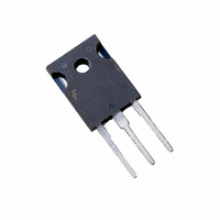
HGTG20N60A4D Fairchild Semiconductor, HGTG20N60A4D Datasheet

HGTG20N60A4D
Specifications of HGTG20N60A4D
HGTG20N60A4D_NL
Available stocks
Related parts for HGTG20N60A4D
HGTG20N60A4D Summary of contents
Page 1
... The much lower on-state voltage drop varies only o o moderately between 25 C and 150 C. The IGBT used is the development type TA49339. The diode used in anti-parallel is the development type TA49372. These IGBT’s are ideal for many high voltage switching ©2002 Fairchild Semiconductor Corporation HGTG20N60A4D, HGT4E20N60A4DS HGTG20N60A4D, HGT4E20N60A4DS Rev. C ...
Page 2
... MIN TYP 600 - 125 1 125 C - 1.6 J 4.5 5 15V, 100 - 15V - 142 20V - 182 105 - 280 - 150 o = 125 105 - 55 - 115 - 510 - 330 HGTG20N60A4D, HGT4E20N60A4DS Rev. C UNITS MAX UNITS - V 250 A 3.0 mA 2.7 V 2.0 V 7.0 V 250 162 nC 210 350 J 200 135 600 J 500 J ...
Page 3
... V , COLLECTOR TO EMITTER VOLTAGE ( 390V 125 GATE TO EMITTER VOLTAGE (V) GE FIGURE 4. SHORT CIRCUIT WITHSTAND TIME HGTG20N60A4D, HGT4E20N60A4DS Rev. C MAX UNITS - 0.43 C/W o 1.9 C/W ON2 500 600 700 450 C 400 350 300 250 200 150 100 14 15 ...
Page 4
... PULSE DURATION = 250 125 150 0.4 0.8 1.2 1 COLLECTOR TO EMITTER VOLTAGE ( 500 390V 125 12V OR 15V COLLECTOR TO EMITTER CURRENT (A) CE EMITTER CURRENT 500 390V 125 125 COLLECTOR TO EMITTER CURRENT (A) CE EMITTER CURRENT HGTG20N60A4D, HGT4E20N60A4DS Rev 2.0 2.4 2.8 = 12V OR 15V 12V 15V ...
Page 5
... COLLECTOR TO EMITTER CURRENT (A) CE CURRENT 1mA 1mA G(REF) G(REF 600V 400V 200V 100 Q , GATE CHARGE (nC) G FIGURE 14. GATE CHARGE WAVEFORMS 125 500 390V TOTAL ON2 OFF 30A 20A 10A CE 0 100 R , GATE RESISTANCE ( ) G HGTG20N60A4D, HGT4E20N60A4DS Rev 120 140 160 = 15V 1000 ...
Page 6
... GATE TO EMITTER VOLTAGE ( GATE TO EMITTER VOLTAGE 90 dI /dt = 200A 125 125 FORWARD CURRENT (A) EC 800 V = 390V CE 600 400 200 0 200 300 400 500 600 700 di /dt, RATE OF CHANGE OF CURRENT ( CURRENT HGTG20N60A4D, HGT4E20N60A4DS Rev 30A 20A 10A 125 125 20A EC o 125 10A ...
Page 7
... Test Circuit and Waveforms L = 500 FIGURE 24. INDUCTIVE SWITCHING TEST CIRCUIT ©2002 Fairchild Semiconductor Corporation Unless Otherwise Specified (Continued) DUTY FACTOR PEAK RECTANGULAR PULSE DURATION (s) 1 HGTG20N60A4D DIODE TA49372 DUT + 390V 90% 10% E ON2 E OFF 90% 10% t d(OFF d(ON)I FIGURE 25. SWITCHING TEST WAVEFORMS HGTG20N60A4D, HGT4E20N60A4DS Rev ...
Page 8
... A 50% duty factor was used (Figure 3) and the D ) are approximated )/2. CE are defined in the switching waveforms OFF is the integral of the ON2 during turn-on and during turn-off. All tail losses are included in the ; i.e., the collector current equals zero OFF HGTG20N60A4D, HGT4E20N60A4DS Rev d(OFF)I ). The ON2 - T )/ ...
Page 9
CROSSVOLT â â â â Rev. H5 ...


