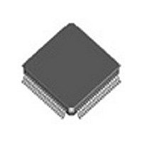
82V2082PF IDT, Integrated Device Technology Inc, 82V2082PF Datasheet - Page 15

82V2082PF
Manufacturer Part Number
82V2082PF
Description
Manufacturer
IDT, Integrated Device Technology Inc
Datasheet
1.82V2082PF.pdf
(88 pages)
Specifications of 82V2082PF
Number Of Transceivers
1
Screening Level
Industrial
Mounting
Surface Mount
Package Type
TQFP
Operating Temperature (min)
-40C
Operating Temperature (max)
85C
Lead Free Status / RoHS Status
Not Compliant
Table-1 Pin Description (Continued)
PIN DESCRIPTION
IDT82V2082
PULS13
PULS12
PULS10
PULS23
PULS22
PULS21
PULS11
Name
LP20
SDO
D7
D6
D5
D4
D3
D2
D1
Type
I/O
I/O
I/O
I/O
I/O
I/O
I/O
O
I
I
I
I
I
I
I
I
TQFP80
Pin No.
43
54
53
52
51
50
49
48
FPBGA81
Pin No.
D8
E7
D9
E8
E9
F9
F5
F6
SDO: Serial Data Output
In serial microcontroller interface mode, this signal is the output data of the serial interface. Configuration or Status data
at SDO pin is clocked out of the device on the rising edge of SCLK if SCLKE pin is low, or on the falling edge of SCLK
if SCLKE pin is high.
In parallel non-multiplexed interface mode, this pin should be left open.
LP21/LP20: loopback mode select for channel 2
See above LP21.
D7: Data Bus bit7
In Intel/Motorola non-multiplexed interface mode, this signal is the bi-directional data bus of the microcontroller interface.
In serial microcontroller interface mode, this pin should be connected to ground through a 10 kΩ resistor.
PULS1[3:0]: these pins are used to select the following functions for channel 1 in hardware control mode:
•
•
•
Refer to
Note that PULS13 to PULS10 determine the T1/E1/J1 mode of common block.
D6: Data Bus bit6
In Intel/Motorola non-multiplexed interface mode, this signal is the bi-directional data bus of the microcontroller interface.
In serial microcontroller interface mode, this pin should be connected to ground through a 10 kΩ resistor.
See above.
D5: Data Bus bit5
In Intel/Motorola non-multiplexed interface mode, this signal is the bi-directional data bus of the microcontroller interface.
In serial microcontroller interface mode, this pin should be connected to ground through a 10 kΩ resistor.
See above.
D4: Data Bus bit4
In Intel/Motorola non-multiplexed interface mode, this signal is the bi-directional data bus of the microcontroller interface.
In serial microcontroller interface mode, this pin should be connected to ground through a 10 kΩ resistor.
See above.
D3: Data Bus bit3
In Intel/Motorola non-multiplexed interface mode, this signal is the bi-directional data bus of the microcontroller interface.
In serial microcontroller interface mode, this pin should be connected to ground through a 10 kΩ resistor.
PULS2[3:0]: these pins are used to select the following functions for channel 2 in hardware control mode:·
•
•
•
Refer to
D2: Data Bus bit2
In Intel/Motorola non-multiplexed interface mode, this signal is the bi-directional data bus of the microcontroller interface.
In serial microcontroller interface mode, this pin should be connected to ground through a 10 kΩ resistor.
See above.
D1: Data Bus bit1
In Intel/Motorola non-multiplexed interface mode, this signal is the bi-directional data bus of the microcontroller interface.
In serial microcontroller interface mode, this pin should be connected to ground through a 10 kΩ resistor.
See above.
T1/E1/J1 mode
Transmit pulse template
Internal termination impedance (75Ω/120Ω/100Ω/110Ω)
T1/E1/J1 mode
Transmit pulse template
Internal termination impedance (75 Ω/120 Ω/100 Ω/110 Ω)
5 HARDWARE CONTROL PIN SUMMARY
5 HARDWARE CONTROL PIN SUMMARY
DUAL CHANNEL T1/E1/J1 LONG HAUL/SHORT HAUL LINE INTERFACE UNIT
15
for details.
for details.
Description
May 4, 2009


