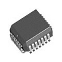
IDT82V1671J IDT, Integrated Device Technology Inc, IDT82V1671J Datasheet - Page 18

IDT82V1671J
Manufacturer Part Number
IDT82V1671J
Description
Manufacturer
IDT, Integrated Device Technology Inc
Datasheet
1.IDT82V1671J.pdf
(107 pages)
Specifications of IDT82V1671J
Number Of Channels
4
On-hook Transmission
Yes
Polarity Reversal
Yes
On-chip Ring Relay Driver
Yes
Operating Supply Voltage (typ)
3.3V
Operating Temp Range
-40C to 85C
Package Type
PLCC
Operating Temperature Classification
Industrial
Pin Count
28
Mounting
Surface Mount
Operating Current
95mA
Operating Supply Voltage (max)
3.465V
Operating Supply Voltage (min)
3.135V
Lead Free Status / RoHS Status
Not Compliant
Available stocks
Company
Part Number
Manufacturer
Quantity
Price
Company:
Part Number:
IDT82V1671J
Manufacturer:
BROADCOM
Quantity:
457
Part Number:
IDT82V1671J
Manufacturer:
IDT
Quantity:
20 000
3.2.5
DC_FEED bit in register LREG5 is set to 1, the default DC feeding
characteristic will be selected (see
is typically for -24 V battery voltage application. When the DC_FEED bit
is set to 0, the DC feeding characteristic is determined by the
coefficients written in the Coe-RAM.
DC feeding. When users input the desired values for I
V
coefficients. When these coefficients are loaded to the Coe-RAM, the
DC feeding characteristic will meet the requirements.
recommended to reduce I
than 5 kΩ when the loop is operated in the constant current zone.
RSLIC & CODEC CHIPSET
K2
The DC feeding characteristic is programmable. When the
IDT provides a software (Cal74) that can calculate the coefficients for
To reduce power consumption and make the DC loop stable, it is
Here is an example for short loop applications (see
R
and V
I
= |(V
I
TIP-RING
Loop resistance < 600 Ω;
I
V
I
MAX
K1
K1
K1
LIM,
= 20 mA (loop current requirement)
DC FEEDING CHARACTERISTICS CONFIGURATION
= 20 V;
– 0)/(I
= 25 mA;
Cal74 will automatically calculate the DC feeding
Figure - 5 Constant Voltage Zone
K1
– I
MAX
MAX
)| = |(20 – 0)/(20 – 25)| = 4 kΩ
and keep the output resistance (R
Figure -
R
V
6). The default configuration
R
L
Figure -
Max,
I
V
K1,
TIP-RING
7):
V
K1,
I
) less
I
K2,
18
I
Figure - 7 DC Feeding Configuration Example for Short Loop
Max
I
I
I
K1
K2
TIP-RING
(25 mA)
Figure - 6 DC Feeding Characteristics Configuration
I
MAX
I
K1
(25 mA)
(20 mA)
14mA
I
TIP-RING
IDT82V1671/IDT82V1671A, IDT82V1074
V
K1
Applications
R
(20 V)
I
V
K1
(18 V, 23 mA)
R
LIN
V
36
K2
(19.5 V, 16 mA)
40 48
R
V
V
LIM
(22 V)
V
TIP-RING
V
TIP-RING


