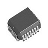
IDT82V1671J IDT, Integrated Device Technology Inc, IDT82V1671J Datasheet - Page 59

IDT82V1671J
Manufacturer Part Number
IDT82V1671J
Description
Manufacturer
IDT, Integrated Device Technology Inc
Datasheet
1.IDT82V1671J.pdf
(107 pages)
Specifications of IDT82V1671J
Number Of Channels
4
On-hook Transmission
Yes
Polarity Reversal
Yes
On-chip Ring Relay Driver
Yes
Operating Supply Voltage (typ)
3.3V
Operating Temp Range
-40C to 85C
Package Type
PLCC
Operating Temperature Classification
Industrial
Pin Count
28
Mounting
Surface Mount
Operating Current
95mA
Operating Supply Voltage (max)
3.465V
Operating Supply Voltage (min)
3.135V
Lead Free Status / RoHS Status
Not Compliant
Available stocks
Company
Part Number
Manufacturer
Quantity
Price
Company:
Part Number:
IDT82V1671J
Manufacturer:
BROADCOM
Quantity:
457
Part Number:
IDT82V1671J
Manufacturer:
IDT
Quantity:
20 000
5
5.1
interface (MPI mode) or GCI monitor channel (GCI mode). In MPI mode,
the command or data is transferred via the CI/CO pin. In GCI mode, the
command or data is transferred via the DD/DU pin.
5.1.1
5.1.1.1
for read-operation). Each channel has its own Channel Enable bit
(CH_EN[0] to CH_EN[3] in GREG4 for Channel 1 to Channel 4,
respectively) to allow individual channel programming. If two or more
CH_EN bits are set to 1 (enable), the corresponding channels are
enabled and can receive the programming information simultaneously.
Therefore, a broadcast mode can be implemented by simply enabling all
of the channels in the device. The broadcast mode is very useful when
initializing a large system, because the registers and RAM locations of
four channels can be configured by one operation.
5.1.1.2
CODEC from other devices in the system. In read operations, before
outputting other data bytes, the CODEC will first output an identification
code of 81H indicating that the following data is from the CODEC.
5.1.2
5.1.2.1
with the master processor through the monitor channel. The messages
transferred in the monitor channel have different data structures. Since
one monitor channel is shared by two voice data channels (channel A
and channel B) to transfer status or control information, a Program Start
(PS) byte is necessary to indicate the source (upstream) channel or the
destination (downstream) channel during data transferring. For a
complete GCI command operation, messages transferred via the
monitor channel always start with a PS byte as follows:
(global/local register command) or a RAM command (FSK-RAM or Coe-
RAM command). For global register commands, the A/B bit in the PS
byte is ignored.
RSLIC & CODEC CHIPSET
Programming the chipset is realized via the serial microprocessor
A broadcast mode is provided for MPI write-operation (not allowed
In MPI mode, an identification code is used to distinguish the
In GCI mode, the CODEC exchanges status and control information
Where, the A/B bit is used to identify the two channels:
A/B = 0: 81H. channel A is the source (upstream) or destination
A/B = 1: 91H. channel B is the source (upstream) or destination
The Program Start byte will be followed by a register command
b7
1
(downstream).
(downstream).
b6
PROGRAMMING
OVERVIEW
MPI PROGRAMMING
Broadcast Mode for MPI Programming
Identification Code for MPI Programming
GCI PROGRAMMING
Program Start Byte for GCI Programming
0
b5
0
A/B
b4
b3
0
b2
0
b1
0
b0
1
59
5.1.2.2
two byte identification command of 8000H is defined for analog line GCI
devices:
IDT82V1074, this two-byte identification code will be 8082H.
5.2
5.2.1
following:
5.2.2
each individual channel. Up to 32 local registers are provided for each
channel. The local registers are accessed by corresponding local
commands.
Register (GREG5) must be first set to specify one or more channels to
be addressed. For example, if the CH_EN[0] bit in GREG4 is set to 1,
the local register(s) of channel 1 will be addressed. The CH_EN[1] to
CH_EN[3] bits enable/disable the local registers of channel 2 to channel
4, respectively, in the same way.
mechanism for addressing the local registers. When executing a local
command, the CODEC will automatically count down from the address
specified in b[4:0] to the address of 0. For example, if b[4:0] = 00001, the
local register with the address of ‘00001' will be accessed first, then the
address will be counted down to ‘00000’ automatically and the
corresponding local register will be accessed. Since the address is
R/W
In order to distinguish different devices unambiguously by software, a
Each device will respond with its specific identification code. For the
For both MPI and GCI modes, the command format is as the
R/W:
CT:
Address: b[4:0] specify the register(s) or the location(s) of RAM to
In both MPI and GCI modes, the local registers are used to configure
• MPI Mode
In MPI mode, when addressing a local register, the Channel Enable
In MPI mode, the CODEC provides an automatic countdown
b7
1
0
1
1
b6
Identification Command for GCI Programming
0
0
0
0
REGISTER/RAM COMMANDS
ADDRESSING THE LOCAL REGISTERS
REGISTER/RAM COMMAND FORMAT
Read/Write Command bit
b7 = 0:
b7 = 1:
Command Type
b6 b5 = 00: Local Register Command
b6 b5 = 01: Global Register Command
b6 b5 = 10: FSK-RAM Command (one word operation)
b6 b5 = 11: Coe-RAM Command (eight words operation)
be addressed.
CT
b5
0
0
0
0
IDT82V1671/IDT82V1671A, IDT82V1074
Read Command
Write Command
b4
0
0
0
0
b3
0
0
0
0
Address
b2
0
0
0
0
b1
0
0
0
1
b0
0
0
0
0


