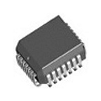
IDT82V1671J IDT, Integrated Device Technology Inc, IDT82V1671J Datasheet - Page 48

IDT82V1671J
Manufacturer Part Number
IDT82V1671J
Description
Manufacturer
IDT, Integrated Device Technology Inc
Datasheet
1.IDT82V1671J.pdf
(107 pages)
Specifications of IDT82V1671J
Number Of Channels
4
On-hook Transmission
Yes
Polarity Reversal
Yes
On-chip Ring Relay Driver
Yes
Operating Supply Voltage (typ)
3.3V
Operating Temp Range
-40C to 85C
Package Type
PLCC
Operating Temperature Classification
Industrial
Pin Count
28
Mounting
Surface Mount
Operating Current
95mA
Operating Supply Voltage (max)
3.465V
Operating Supply Voltage (min)
3.135V
Lead Free Status / RoHS Status
Not Compliant
Available stocks
Company
Part Number
Manufacturer
Quantity
Price
Company:
Part Number:
IDT82V1671J
Manufacturer:
BROADCOM
Quantity:
457
Part Number:
IDT82V1671J
Manufacturer:
IDT
Quantity:
20 000
start voltage and increases its voltage following the programmed slope.
When the voltage of the ramp signal finally reaches the programmed
end voltage, the RAMP_OK bit in LREG21 will be set to indicate that the
Table - 18 Registers and Coe-RAM Locations Used for Ramp Generator
refer to
the level meter. The capacitance then can be calculated as:
enabled after the current has settled to a constant value. The integration
time is programmed by the LM_CN[10:0] bits in GREG15 and GREG16.
3.9.6.6
Ramp Parameters Selection
Ramp Start Voltage
Ramp Slope
Ramp End Voltage
Ramp Mode Selection
Ramp Generator Enable
Ramp Over Indication
Mask bit for RAMP_OK
RSLIC & CODEC CHIPSET
4. Enable the ramp generator (LREG8: RAMP_EN = 1).
Once the RAMP_EN bit is set to 1, a ramp signal will start from the
• Capacitance Measurement
The sequence of capacitance measurement is as the following (also
1. Configure the ramp generator (program the ramp slope, start
2. Select the VTDC voltage to the DC level meter;
3. Configure the level meter integrator (GREG16: LM_ONCE = 1);
4. Enable the ramp generator (LREG8: RAMP_EN = 1);
5. After the current has settled, enable the level meter (GREG16:
6. Read the result in GREG17 and GREG18.
The actual current can be calculated as: i(t) = C
Where, dU/dt is the ramp slope and i(t) is the current measured by
To ensure measurement accuracy, the level meter integrator must be
The DC level meter can measure the following voltages:
• External voltage Tip/GND (through IO4 pin)
• External voltage Ring/GND (through IO3 pin)
• External voltage Tip/Ring (through IO4 -IO3)
• Ringing voltage (through IO4 -IO3)
• Supply voltage VDD of the CODEC
The two programmable IO pins (IO3 and IO4) with analog input
C
Measure
voltage and end voltage);
LM_EN = 1).
(Note: The ramp voltage starts at RingOffset and ramps up/down
until RampEnd is reached. When the integration is finished, the
result will be stored in registers GREG17 and GREG18).
Figure -
Parameter
=
Voltage Measurement
------------------------ -
(
26):
du
i t ( )
)
⁄
( )
dt
=
Word RingOffset in the Coe-RAM
Word RampSlope in the Coe-RAM
Bit RG in LREG5
Word RampEnd in the Coe-RAM
Bit RAMP in LREG6
Bit RAMP_EN in LREG8
Bit RAMP_OK in LREG21
Bit RAMP_M in LREG18
Register Bits/Coe-RAM Words
---------------------------------------------------------------------------- -
K
ADDC
×
K
INT
LM
×
Result
N
Samples
Measure
×
K
ITDC
× dU/dt
⁄
RG = 0: The ramp slope, start voltage and end voltage in the Coe-RAM are selected.
RG = 1: The ramp slope, start voltage and end voltage in the ROM are selected (default);
Programmable from -70 V to 70 V with
Programmable from 20 V/s to 2000 V/s with
V/s.
Programmable from -70 V to 70 V with
The ramp signal can only be generated in the RAMP mode (RAMP = 1).
RAMP_EN = 0: The ramp generator is disabled;
RAMP_EN = 1: The ramp generator is enabled.
RAMP_OK = 0: The ramp generation is in progress;
RAMP_OK = 1: The ramp generation is finished.
RAMP_M = 0: An interrupt will be generated when the RAMP_OK bit changes from 0 to 1;
RAMP_M = 1: Interrupts will not be generated when the RAMP_OK bit changes.
du
----- -
dt
48
ramp generation is finished. An interrupt will be generated
simultaneously if the ramp mask bit RAMP_M in LREG18 is 0.
generation.
functionality can be used to measure external voltages. If IO3 and IO4
pins are connected properly over a voltage divider to the Ring and Tip
lines, the external voltage supplied to the lines can be measured on
either IO3 or IO4 pin, or on IO4-IO3 (differential measurement). The
LM_SEL[3:0] bits in LREG9 select an external voltage to be measured.
Refer to
external voltage measurements at the Ring and Tip lines.
reference to VCM):
Voltage Source
Table - 18
Figure - 27
The voltage measured on IO3, IO4 or IO4-IO3 is as follows (with a
External
Figure - 27 External Voltage Measurement Principle
Table - 13 on page 40
V
AC
DC
IO4
lists the registers and Coe-RAM locations used for ramp
shows the connection and external resistors used for
=
------------------------------------------------------ - VCM
K
±
±
Line Card
ADDC
1% tolerance. The default value in the ROM is 7 V.
1% tolerance. The default value in the ROM is 20 V.
R2
R1
R3
R4
±
IDT82V1671/IDT82V1671A, IDT82V1074
Notes
1% tolerance. The default value in the ROM is 300
×
LM
K
R
R
Sense
Sense
INT
for details.
VCM
Result
VCM
×
N
RSLIC
Samples
+
VTDC
DCP
DCN
VL
CODEC
IO4
IO3


