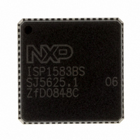
ISP1583BSUM ST-Ericsson Inc, ISP1583BSUM Datasheet - Page 53

ISP1583BSUM
Manufacturer Part Number
ISP1583BSUM
Description
IC USB PERIPH CONTROLLER 64HVQFN
Manufacturer
ST-Ericsson Inc
Datasheet
1.ISP1583BSUM.pdf
(100 pages)
Specifications of ISP1583BSUM
Controller Type
USB Peripheral Controller
Interface
Parallel/Serial
Voltage - Supply
3 V ~ 3.6 V
Current - Supply
47mA
Operating Temperature
-40°C ~ 85°C
Mounting Type
Surface Mount
Package / Case
64-VQFN Exposed Pad, 64-HVQFN, 64-SQFN, 64-DHVQFN
Lead Free Status / RoHS Status
Lead free / RoHS Compliant
Other names
568-1886-2
ISP1583BS,518
ISP1583BS-T
ISP1583BS,518
ISP1583BS-T
Available stocks
Company
Part Number
Manufacturer
Quantity
Price
Company:
Part Number:
ISP1583BSUM
Manufacturer:
MICRON
Quantity:
2 000
Company:
Part Number:
ISP1583BSUM
Manufacturer:
ST-ERICS
Quantity:
829
Part Number:
ISP1583BSUM
Manufacturer:
STE
Quantity:
20 000
NXP Semiconductors
Table 58.
ISP1583_7
Product data sheet
Bit
Symbol
Reset
Bus reset
Access
DMA Hardware register: bit allocation
9.4.4 DMA Hardware register (address: 3Ch)
R/W
7
0
0
ENDIAN[1:0]
[2]
The DMA Hardware register consists of 1 byte. The bit allocation is shown in
This register determines the polarity of bus control signals (EOT, DACK, DREQ, DIOR and
DIOW) and DMA mode (master or slave). It also controls whether the upper and lower
parts of the data bus are swapped (bits ENDIAN[1:0]), for modes GDMA (slave) and
MDMA (master) only.
Table 59.
Bit
7 to 6
5
4
3
PIO read or write that started using the DMA Command register only performs 16-bit transfer.
R/W
6
0
0
Symbol
ENDIAN[1:0] Endian: These bits determine whether the data bus is swapped between
EOT_POL
MASTER
ACK_POL
DMA Hardware register: bit description
EOT_POL
R/W
5
0
0
Rev. 07 — 22 September 2008
Description
the internal RAM and the DMA bus. This only applies for modes GDMA
(slave) and MDMA (master).
00 — Normal data representation; 16-bit bus: MSByte on DATA[15:8] and
LSByte on DATA[7:0].
01 — Swapped data representation; 16-bit bus: MSByte on DATA[7:0] and
LSByte on DATA[15:8].
10 — reserved
11 — reserved
Remark: While operating with the 8-bit data bus, bits ENDIAN[1:0] must
always be set to logic 00.
EOT Polarity: Selects the polarity of the End-Of-Transfer input; used in
GDMA slave mode only.
0 — EOT is active LOW
1 — EOT is active HIGH
Master or Slave Selection: Selects DMA master or slave mode.
0 — GDMA slave mode
1 — MDMA master mode
Acknowledgment Polarity: Selects the DMA acknowledgment polarity.
0 — DACK is active LOW
1 — DACK is active HIGH
MASTER
R/W
4
0
0
ACK_POL
R/W
3
0
0
Hi-Speed USB peripheral controller
DREQ_
POL
R/W
2
1
1
WRITE_
POL
R/W
1
0
0
© NXP B.V. 2008. All rights reserved.
ISP1583
Table
READ_
POL
R/W
0
0
0
52 of 99
58.


