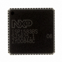
ISP1583BSUM ST-Ericsson Inc, ISP1583BSUM Datasheet - Page 59

ISP1583BSUM
Manufacturer Part Number
ISP1583BSUM
Description
IC USB PERIPH CONTROLLER 64HVQFN
Manufacturer
ST-Ericsson Inc
Datasheet
1.ISP1583BSUM.pdf
(100 pages)
Specifications of ISP1583BSUM
Controller Type
USB Peripheral Controller
Interface
Parallel/Serial
Voltage - Supply
3 V ~ 3.6 V
Current - Supply
47mA
Operating Temperature
-40°C ~ 85°C
Mounting Type
Surface Mount
Package / Case
64-VQFN Exposed Pad, 64-HVQFN, 64-SQFN, 64-DHVQFN
Lead Free Status / RoHS Status
Lead free / RoHS Compliant
Other names
568-1886-2
ISP1583BS,518
ISP1583BS-T
ISP1583BS,518
ISP1583BS-T
Available stocks
Company
Part Number
Manufacturer
Quantity
Price
Company:
Part Number:
ISP1583BSUM
Manufacturer:
MICRON
Quantity:
2 000
Company:
Part Number:
ISP1583BSUM
Manufacturer:
ST-ERICS
Quantity:
829
Part Number:
ISP1583BSUM
Manufacturer:
STE
Quantity:
20 000
NXP Semiconductors
Table 76.
Table 78.
ISP1583_7
Product data sheet
Bit
Symbol
Reset
Bus reset
Access
Bit
Symbol
Reset
Bus reset
Access
DMA Endpoint register: bit allocation
DMA Strobe Timing register: bit allocation
9.4.9 DMA Strobe Timing register (address: 60h)
7
7
-
-
-
-
-
-
Table 77.
The DMA Endpoint register must not reference the endpoint that is indexed by the
Endpoint Index register (2Ch) at any time. Doing so will result in data corruption.
Therefore, if the DMA Endpoint register is unused, point it to an unused endpoint. If the
DMA Endpoint register, however, is pointed to an active endpoint, the firmware must not
reference the same endpoint on the Endpoint Index register.
This 1-byte register controls the strobe timing for MDMA mode, when bits
DMA_MODE[1:0] in the DMA Configuration register have been set to 03h.
The bit allocation is given in
Table 79.
[1]
Bit
7 to 4
3 to 1
0
Bit
7 to 5
4 to 0
The cycle duration indicates the internal clock cycle (33.3 ns/cycle).
reserved
6
6
-
-
-
-
-
-
Symbol
-
DMA_STROBE_
CNT[4:0]
reserved
DMA Endpoint register: bit description
DMA Strobe Timing register: bit description
Symbol
-
EPIDX[2:0]
DMADIR
5
5
-
-
-
-
-
-
Rev. 07 — 22 September 2008
Description
reserved
DMA Strobe Count: These bits select the strobe duration for
DMA_MODE = 03h (see
cycles
Figure
Description
reserved
Endpoint Index: selects the indicated endpoint for DMA access
DMA Direction:
0 — Selects the RX/OUT FIFO for DMA read transfers
1 — Selects the TX/IN FIFO for DMA write transfers
Table
R/W
[1]
4
4
1
1
-
-
-
17).
, with N representing the value of DMA_STROBE_CNT (see
78.
R/W
R/W
3
0
0
3
1
1
DMA_STROBE_CNT[4:0]
Table
Hi-Speed USB peripheral controller
EPIDX[2:0]
56). The strobe duration is (N + 1)
R/W
R/W
2
0
0
2
1
1
R/W
R/W
1
0
0
1
1
1
© NXP B.V. 2008. All rights reserved.
ISP1583
DMADIR
R/W
R/W
0
0
0
0
1
1
58 of 99


