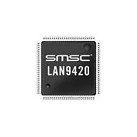
LAN9420I-NU SMSC, LAN9420I-NU Datasheet - Page 39

LAN9420I-NU
Manufacturer Part Number
LAN9420I-NU
Description
IC ETHERNET CTRLR SGL 128VTQFP
Manufacturer
SMSC
Type
Single Chip MAC and PHY Controllerr
Specifications of LAN9420I-NU
Controller Type
Ethernet Controller
Interface
PCI
Voltage - Supply
3 V ~ 3.6 V
Current - Supply
145mA
Operating Temperature
-40°C ~ 85°C
Mounting Type
Surface Mount
Package / Case
128-TQFP, 128-VQFP
Product
Ethernet Controllers
Number Of Transceivers
1
Standard Supported
802.3, 802.3u
Data Rate
10 MB, 100 MB
Supply Voltage (max)
3.6 V
Supply Voltage (min)
1.6 V
Maximum Operating Temperature
+ 85 C
Ethernet Connection Type
10/100 Base-T
Minimum Operating Temperature
- 40 C
Mounting Style
SMD/SMT
Lead Free Status / Rohs Status
Lead free / RoHS Compliant
Other names
638-1085
Available stocks
Company
Part Number
Manufacturer
Quantity
Price
Company:
Part Number:
LAN9420I-NU
Manufacturer:
Standard
Quantity:
368
Company:
Part Number:
LAN9420I-NU
Manufacturer:
SMSC
Quantity:
7 468
Company:
Part Number:
LAN9420I-NU
Manufacturer:
Microchip Technology
Quantity:
10 000
Single-Chip Ethernet Controller with HP Auto-MDIX Support and PCI Interface
Datasheet
SMSC LAN9420/LAN9420i
The DMAC transfers RX data frames to the RX buffers in Host memory and transmits data from TX
buffers in the Host memory. Descriptors that reside in Host memory contain pointers to these buffers.
There are two DMA descriptor lists; one for receive operations and one for transmit operations. The
base address of each list is written into the RX_BASE_ADDR and TX_BASE_ADDR registers,
respectively. A descriptor list is forward linked (either implicitly or explicitly). Descriptors are usually
placed in the physical memory in an incrementing and a contiguous addressing scheme. However, the
last descriptor may point back to the first entry to create a ring structure. Explicit chaining of descriptors
is accomplished by setting the Second Address Chained flag in both receive and transmit descriptors
(RCH - RDES1[24] and TCH - TDES1[24]). Each descriptor's list resides in Host memory. Each
descriptor can point to a maximum of two buffers. This enables the use of two physically addressed,
as well as non-contiguous memory buffers.
Data buffers reside in the Host memory space. An Ethernet frame can be fragmented across multiple
data buffers, but a data buffer cannot contain more than one Ethernet frame. Data chaining refers to
Ethernet frames that span multiple data buffers. Data buffers contain only data used in the Ethernet
frame. The buffer status is maintained in the descriptor. In a ring structure, each descriptor can point
to up to two data buffers with the restriction that both buffers contain data for the same Ethernet frame.
In a chain structure, each descriptor points to a single data buffer and to the next descriptor in the
chain.
The DMAC will skip to the next frame buffer when end of frame is detected. Data chaining can be
enabled or disabled. The ring and chain type descriptor structures are illustrated in
Note: Descriptors of zero buffer length are not supported at the initial and final descriptors of a chain.
Descriptor lists and data buffers, described in this chapter.
DATASHEET
39
Revision 1.4 (12-17-08)
Figure
3.15.


