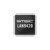
LAN9420I-NU SMSC, LAN9420I-NU Datasheet - Page 49

LAN9420I-NU
Manufacturer Part Number
LAN9420I-NU
Description
IC ETHERNET CTRLR SGL 128VTQFP
Manufacturer
SMSC
Type
Single Chip MAC and PHY Controllerr
Specifications of LAN9420I-NU
Controller Type
Ethernet Controller
Interface
PCI
Voltage - Supply
3 V ~ 3.6 V
Current - Supply
145mA
Operating Temperature
-40°C ~ 85°C
Mounting Type
Surface Mount
Package / Case
128-TQFP, 128-VQFP
Product
Ethernet Controllers
Number Of Transceivers
1
Standard Supported
802.3, 802.3u
Data Rate
10 MB, 100 MB
Supply Voltage (max)
3.6 V
Supply Voltage (min)
1.6 V
Maximum Operating Temperature
+ 85 C
Ethernet Connection Type
10/100 Base-T
Minimum Operating Temperature
- 40 C
Mounting Style
SMD/SMT
Lead Free Status / Rohs Status
Lead free / RoHS Compliant
Other names
638-1085
Available stocks
Company
Part Number
Manufacturer
Quantity
Price
Company:
Part Number:
LAN9420I-NU
Manufacturer:
Standard
Quantity:
368
Company:
Part Number:
LAN9420I-NU
Manufacturer:
SMSC
Quantity:
7 468
Company:
Part Number:
LAN9420I-NU
Manufacturer:
Microchip Technology
Quantity:
10 000
Single-Chip Ethernet Controller with HP Auto-MDIX Support and PCI Interface
Datasheet
SMSC LAN9420/LAN9420i
3.4.3
BITS
31:0
BITS
31:0
Transmit Descriptor 2 (TDES2)
Transmit Descriptor 3 (TDES3)
Initialization
The following sequence explains the initialization steps for the DMA controller and activation of the
receive and transmit paths:
1. Configure the BUS_MODE register.
2. Mask unnecessary interrupts by writing to the DMAC_INTR_ENA register.
3. Software
4. Write DMAC_CONTROL to set bits 13 (ST) and 1 (SR) to start the TX and RX DMA. The TX and
5. Set bit 2 (RXEN) of MAC_CR to turn the receiver on.
6. Set bit 3 (TXEN) of MAC_CR to turn the transmitter on.
TX_BASE_ADDR after the RX and TX descriptor lists are created.
RX engines enter the running state and attempt to acquire descriptors from the respective
descriptor lists. The receive and transmit engines begin processing receive and transmit
operations.
Buffer 1 Address Pointer
This is the physical address of buffer 1. There are no limitations on the buffer address alignment.
Host Actions: Initializes this field.
DMAC Actions: Reads this field upon opening a new DMA descriptor to obtain the buffer
address.
Buffer 2 Address Pointer (Next Descriptor Address)
The TCH (Second Address Chained) bit (TDES1[24]) determines the usage of this field as
follows:
TCH is zero: This field contains the pointer to the address of buffer 2 in Host memory. There
are no limitations on buffer address alignment.
TCH is one: Descriptor chaining is in use and this field contains the pointer to the next
descriptor in Host memory. The descriptor must be 4-DWORD (16-byte) aligned (TDES3[3:0] =
0000b). In the case where the buffer is not 4-DWORD aligned, the resulting behavior is
undefined.
Note:
Host Actions: Initializes this field.
DMAC Actions: Reads this field upon opening a new DMA descriptor to obtain the buffer
address.
If TER (TDES1[25]) is set, TCH is ignored and this field is treated as a pointer to buffer
2 as in the “TCH is zero” case above.
driver
writes
Table 3.11 TDES2 Bit Fields
Table 3.12 TDES3 Bit Fields
to
DATASHEET
descriptor
49
DESCRIPTION
DESCRIPTION
base
address
registers
RX_BASE_ADDR
Revision 1.4 (12-17-08)
and


