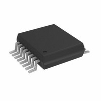
AD5933YRSZ Analog Devices Inc, AD5933YRSZ Datasheet - Page 16

AD5933YRSZ
Manufacturer Part Number
AD5933YRSZ
Description
IC NTWK ANALYZER 12B 1MSP 16SSOP
Manufacturer
Analog Devices Inc
Datasheet
1.AD5933YRSZ.pdf
(44 pages)
Specifications of AD5933YRSZ
Resolution (bits)
12 b
Master Fclk
16.776MHz
Voltage - Supply
2.7 V ~ 5.5 V
Operating Temperature
-40°C ~ 125°C
Mounting Type
Surface Mount
Package / Case
16-SSOP
Supply Voltage Range
2.7V To 5.5V
Operating Temperature Range
-40°C To +125°C
Digital Ic Case Style
SSOP
No. Of Pins
16
Frequency Max
0.1MHz
Termination Type
SMD
Pin Count
16
Screening Level
Automotive
Package Type
SSOP
Filter Terminals
SMD
Rohs Compliant
Yes
Communication Function
Network Analyzer
Lead Free Status / RoHS Status
Lead free / RoHS Compliant
For Use With
EVAL-AD5933EBZ - BOARD EVALUATION FOR AD5933
Tuning Word Width (bits)
-
Lead Free Status / Rohs Status
Compliant
Other names
AD5933BRSZ
Q2204656A
Q2204656A
Available stocks
Company
Part Number
Manufacturer
Quantity
Price
Company:
Part Number:
AD5933YRSZ
Manufacturer:
ADI
Quantity:
5 000
Company:
Part Number:
AD5933YRSZ
Manufacturer:
Fujitsu
Quantity:
500
Part Number:
AD5933YRSZ
Manufacturer:
ADI/亚德诺
Quantity:
20 000
AD5933
SYSTEM CLOCK
The system clock for the AD5933 can be provided in one of two
ways. The user can provide a highly accurate and stable system
clock at the external clock pin (MCLK). Alternatively, the AD5933
provides an internal clock with a typical frequency of 16.776 MHz
by means of an on-chip oscillator.
The user can select the preferred system clock by programming
Bit D3 in the control register (Register Address 0x81, see
Table 11). The default clock option on power-up is selected to
be the internal oscillator.
The frequency distribution of the internal clock with temperature
can be seen in Figure 14, Figure 15, and Figure 16.
TEMPERATURE SENSOR
The temperature sensor is a 13-bit digital temperature sensor with
a 14
allows an accurate measurement of the ambient device temper-
ature to be made.
The measurement range of the sensor is −40°C to +125°C. At
+150°C, the structural integrity of the device starts to deteriorate
when operated at voltage and temperature maximum specifica-
tions. The accuracy within the measurement range is ±2°C.
TEMPERATURE CONVERSION DETAILS
The conversion clock for the part is internally generated; no
external clock is required except when reading from and writing
to the serial port. In normal mode, an internal clock oscillator
runs an automatic conversion sequence.
The temperature sensor block defaults to a power-down state.
To perform a measurement, a measure temperature command
is issued by the user to the control register (Register Address 0x80
and Register Address 0x81). After the temperature operation is
complete (typically 800 μs later), the block automatically
powers down until the next temperature command is issued.
The user can poll the status register (Register Address 0x8F) to see
if a valid temperature conversion has taken place, indicating that
valid temperature data is available to read at Register Address
0x92 and Register Address 0x93 (see the Register Map section).
TEMPERATURE VALUE REGISTER
The temperature value register is a 16-bit, read-only register that
stores the temperature reading from the ADC in 14-bit, twos
complement format. The two MSB bits are don’t cares. D13 is the
sign bit. The internal temperature sensor is guaranteed to a low
value limit of –40°C and a high value limit of +150°C. The digital
output stored in Register Address 0x92 and Register Address 0x93
for the various temperatures is outlined in Table 6. The tempera-
ture sensor transfer characteristic is shown in Figure 21.
th
bit that acts as a sign bit. The on-chip temperature sensor
Rev. C | Page 16 of 44
Table 6. Temperature Data Format
Temperature
−40°C
−30°C
−25°C
−10°C
−0.03125°C
0°C
+0.03125°C
+10°C
+25°C
+50°C
+75°C
+100°C
+125°C
+150°C
TEMPERATURE CONVERSION FORMULA
where ADC Code uses all 14 bits of the data byte, including the
sign bit.
where ADC Code (D) is D13, the sign bit, and is removed from the
ADC code.)
01, 0010, 1100, 0000
00, 1001, 0110, 0000
00, 0000, 0000, 0001
–40°C
Positive Temperature = ADC Code (D)/32
Negative Temperature = (ADC Code (D)
Negative Temperature = (ADC Code (D)
–30°C
–0.03125°C
Figure 21. Temperature Sensor Transfer Function
11, 1111, 1111, 1111
11, 1100, 0100, 0000
11, 1011, 0000, 0000
Digital Output D13…D0
11, 1011, 0000, 0000
11, 1100, 0100, 0000
11, 1100, 1110, 0000
11, 1110, 1100, 0000
11, 1111, 1111, 1111
00, 0000, 0000, 0000
00, 0000, 0000, 0001
00, 0001, 0100, 0000
00, 0011, 0010, 0000
00, 0110, 0100, 0000
00, 1001, 0110, 0000
00, 1100, 1000, 0000
00, 1111, 1010, 0000
01, 0010, 1100, 0000
TEMPERATURE (°C)
75°C
–
–
16384)/32
8192)/32
150°C


