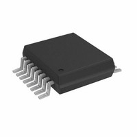
AD5933YRSZ Analog Devices Inc, AD5933YRSZ Datasheet - Page 29

AD5933YRSZ
Manufacturer Part Number
AD5933YRSZ
Description
IC NTWK ANALYZER 12B 1MSP 16SSOP
Manufacturer
Analog Devices Inc
Datasheet
1.AD5933YRSZ.pdf
(44 pages)
Specifications of AD5933YRSZ
Resolution (bits)
12 b
Master Fclk
16.776MHz
Voltage - Supply
2.7 V ~ 5.5 V
Operating Temperature
-40°C ~ 125°C
Mounting Type
Surface Mount
Package / Case
16-SSOP
Supply Voltage Range
2.7V To 5.5V
Operating Temperature Range
-40°C To +125°C
Digital Ic Case Style
SSOP
No. Of Pins
16
Frequency Max
0.1MHz
Termination Type
SMD
Pin Count
16
Screening Level
Automotive
Package Type
SSOP
Filter Terminals
SMD
Rohs Compliant
Yes
Communication Function
Network Analyzer
Lead Free Status / RoHS Status
Lead free / RoHS Compliant
For Use With
EVAL-AD5933EBZ - BOARD EVALUATION FOR AD5933
Tuning Word Width (bits)
-
Lead Free Status / Rohs Status
Compliant
Other names
AD5933BRSZ
Q2204656A
Q2204656A
Available stocks
Company
Part Number
Manufacturer
Quantity
Price
Company:
Part Number:
AD5933YRSZ
Manufacturer:
ADI
Quantity:
5 000
Company:
Part Number:
AD5933YRSZ
Manufacturer:
Fujitsu
Quantity:
500
Part Number:
AD5933YRSZ
Manufacturer:
ADI/亚德诺
Quantity:
20 000
WRITING/READING TO THE AD5933
The interface specification defines several different protocols
for different types of read and write operations. This section
describes the protocols used in the AD5933. The figures in this
section use the abbreviations shown in Table 15.
Table 15. I
Abbreviation
S
P
R
W
A
A
User Command Codes
The command codes in Table 16 are used for reading/writing to
the interface. They are further explained in this section, but are
grouped here for easy reference.
Table 16. Command Codes
Command
Code
1010 0000
1010 0001
1011 0000
Write Byte/Command Byte
In this operation, the master device sends a byte of data to the
slave device. The write byte can either be a data byte write to a
register address or can be a command operation. To write data
to a register, the command sequence is as follows (see Figure 36):
1.
2.
3.
4.
5.
6.
7.
8.
The master device asserts a start condition on SDA.
The master sends the 7-bit slave address followed by the
write bit (low).
The addressed slave device asserts an acknowledge on SDA.
The master sends a register address.
The slave asserts an acknowledge on SDA.
The master sends a data byte.
The slave asserts an acknowledge on SDA.
The master asserts a stop condition on SDA to end the
transaction.
2
C Abbreviation Table
Code
Name
Block
write
Block
read
Address
pointer
Condition
Start
Stop
Read
Write
Acknowledge
No acknowledge write byte/command byte
S
Code Description
This command is used when writing
multiple bytes to the RAM; see the
Block Write section.
This command is used when reading
multiple bytes from RAM/memory;
see the Block Read section.
This command enables the user to set
the address pointer to any location in
the memory. The data contains the
address of the register to which the
pointer should be pointing reworded
ADDRESS
SLAVE
W
A
BLOCK
WRITE
A
Figure 38. Writing a Block Write
BYTES WRITE
NUMBER
Rev. C | Page 29 of 44
A
The write byte protocol is also used to set a pointer to an
address (see Figure 37). This is used for a subsequent single-
byte read from the same address or block read or block write
starting at that address.
To set a register pointer, the following sequence is applied:
1.
2.
3.
4.
5.
6.
7.
8.
BLOCK WRITE
In this operation, the master device writes a block of data to a
slave device (see Figure 38). The start address for a block write
must previously have been set. In the case of the AD5933 this is
done by setting a pointer to set the register address.
1.
2.
3.
4.
5.
6.
7.
8.
9.
10. The master asserts a stop condition on SDA to end the
BYTE 0
S
The master device asserts a start condition on SDA.
The master sends the 7-bit slave address followed by the
write bit (low).
The addressed slave device asserts an acknowledge on
SDA.
The master sends a pointer command code (see Table 16;
a pointer command = 1011 0000).
The slave asserts an acknowledge on SDA.
The master sends a data byte (a register address to where
the pointer is to point).
The slave asserts an acknowledge on SDA.
The master asserts a stop condition on SDA to end the
transaction.
The master device asserts a start condition on SDA.
The master sends the 7-bit slave address followed by the
write bit (low).
The addressed slave device asserts an acknowledge on SDA.
The master sends an 8-bit command code (1010 0000) that
tells the slave device to expect a block write.
The slave asserts an acknowledge on SDA.
The master sends a data byte that tells the slave device the
number of data bytes to be sent to it.
The slave asserts an acknowledge on SDA.
The master sends the data bytes.
The slave asserts an acknowledge on SDA after each
data byte.
transaction.
S
ADDRESS
SLAVE
Figure 37. Setting Address Pointer to Register Address
A
ADDRESS
Figure 36. Writing Register Data to Register Address
SLAVE
BYTE 1
W
W
A
A
A
COMMAND
1011 0000
BYTE 2
POINTER
REGISTER
ADDRESS
A
A
P
A
TO POINT TO
REGISTER
ADDRESS
REGISTER
DATA
AD5933
A
A
P
P


