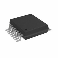
AD5933YRSZ Analog Devices Inc, AD5933YRSZ Datasheet - Page 22

AD5933YRSZ
Manufacturer Part Number
AD5933YRSZ
Description
IC NTWK ANALYZER 12B 1MSP 16SSOP
Manufacturer
Analog Devices Inc
Datasheet
1.AD5933YRSZ.pdf
(44 pages)
Specifications of AD5933YRSZ
Resolution (bits)
12 b
Master Fclk
16.776MHz
Voltage - Supply
2.7 V ~ 5.5 V
Operating Temperature
-40°C ~ 125°C
Mounting Type
Surface Mount
Package / Case
16-SSOP
Supply Voltage Range
2.7V To 5.5V
Operating Temperature Range
-40°C To +125°C
Digital Ic Case Style
SSOP
No. Of Pins
16
Frequency Max
0.1MHz
Termination Type
SMD
Pin Count
16
Screening Level
Automotive
Package Type
SSOP
Filter Terminals
SMD
Rohs Compliant
Yes
Communication Function
Network Analyzer
Lead Free Status / RoHS Status
Lead free / RoHS Compliant
For Use With
EVAL-AD5933EBZ - BOARD EVALUATION FOR AD5933
Tuning Word Width (bits)
-
Lead Free Status / Rohs Status
Compliant
Other names
AD5933BRSZ
Q2204656A
Q2204656A
Available stocks
Company
Part Number
Manufacturer
Quantity
Price
Company:
Part Number:
AD5933YRSZ
Manufacturer:
ADI
Quantity:
5 000
Company:
Part Number:
AD5933YRSZ
Manufacturer:
Fujitsu
Quantity:
500
Part Number:
AD5933YRSZ
Manufacturer:
ADI/亚德诺
Quantity:
20 000
AD5933
A plot showing the AD5933 system phase response calculated
using a 220 kΩ calibration resistor (R
and the repeated phase measurement with a 10 pF capacitive
impedance is shown in Figure 32.
One important point to note about the phase formula used to
plot Figure 32 is that it uses the arctangent function that returns
a phase angle in radians and, therefore, it is necessary to convert
from radians to degrees.
The phase difference (that is, ZØ) between the phase response
of a capacitor and the system phase response using a resistor is
the impedance phase of the capacitor, ZØ (see Figure 33).
Also when using the real and imaginary values to interpret
the phase at each measurement point, take care when using
the arctangent formula. The arctangent function returns the
correct standard phase angle only when the sign of the real and
imaginary values are positive, that is, when the coordinates lie
–100
–90
–80
–70
–60
–50
–40
–30
–20
–10
200
180
160
140
120
100
80
60
40
20
0
0
0
0
Figure 32. System Phase Response vs. Capacitive Phase
15k
15k
Figure 33. Phase Response of a Capacitor
30k
30k
220kΩ RESISTOR
10pF CAPACITOR
45k
45k
FREQUENCY (Hz)
FREQUENCY (Hz)
60k
60k
FB
75k
75k
= 220 kΩ, PGA = ×1)
90k
90k
105k
105k
120k
120k
Rev. C | Page 22 of 44
in the first quadrant. The standard angle is the angle taken
counterclockwise from the positive real x-axis. If the sign of the
real component is positive and the sign of the imaginary
component is negative, that is, the data lies in the second
quadrant, then the arctangent formula returns a negative angle
and it is necessary to add a further 180 degrees to calculate the
correct standard angle. Likewise, when the real and imaginary
components are both negative, that is, when the coordinates lie
in the third quadrant, then the arctangent formula returns a
positive angle and it is necessary to add 180 degrees from the
angle to return the correct standard phase. Finally, when the
real component is positive and the imaginary component is
negative, that is, the data lies in the fourth quadrant, then the
arctangent formula returns a negative angle. It is necessary to
add 360 degrees to the angle to calculate the correct phase
angle.
Therefore, the correct standard phase angle is dependent upon
the sign of the real and imaginary component and is summa-
rized in Table 7.
Once the magnitude of the impedance (|Z|) and the impedance
phase angle (ZØ, in radians) are correctly calculated, it is possible
to determine the magnitude of the real (resistive) and imaginary
(reactive) component of the impedance (Z
vector projection of the impedance magnitude onto the real
and imaginary impedance axis using the following formulas:
The real component is given by
The imaginary component is given by
Table 7. Phase Angle
Real
Positive
Positive
Negative
Positive
| Z
| Z
REAL
IMAG
| = | Z | × cos ( Z Ø)
| = | Z | × sin ( Z Ø)
Imaginary
Positive
Negative
Negative
Negative
Quadrant
First
Third
Fourth
Second
Phase Angle
180
180
360
tan
−
°
°
°
1
+
+
+
(
UNKNOWN
I
⎛
⎜
⎝
⎛
⎜
⎝
⎛
⎜
⎝
/
tan
tan
tan
R
)
×
−
−
−
1
1
1
180
(
(
(
) by the
I
I
I
π
/
/
/
R
R
°
R
)
)
)
×
×
×
180
180
180
π
π
π
°
°
°
⎞
⎟
⎠
⎞
⎟
⎠
⎞
⎟
⎠


