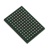
VSC8211XVW Vitesse Semiconductor Corp, VSC8211XVW Datasheet - Page 104

VSC8211XVW
Manufacturer Part Number
VSC8211XVW
Description
IC PHY 10/100/1000 SGL 117-LBGA
Manufacturer
Vitesse Semiconductor Corp
Type
PHY Transceiverr
Specifications of VSC8211XVW
Number Of Drivers/receivers
1/1
Protocol
Gigabit Ethernet
Voltage - Supply
3 V ~ 3.6 V
Mounting Type
Surface Mount
Package / Case
117-LBGA
Case
BGA
Dc
07+
Lead Free Status / RoHS Status
Lead free / RoHS Compliant
Other names
907-1023
Available stocks
Company
Part Number
Manufacturer
Quantity
Price
Company:
Part Number:
VSC8211XVW
Manufacturer:
VITESSE
Quantity:
5
Company:
Part Number:
VSC8211XVW
Manufacturer:
Semtech
Quantity:
3 413
Company:
Part Number:
VSC8211XVW
Manufacturer:
VITESSE
Quantity:
648
Company:
Part Number:
VSC8211XVW
Manufacturer:
Vitesse Semiconductor Corporation
Quantity:
10 000
Part Number:
VSC8211XVW
Manufacturer:
VITESSE
Quantity:
20 000
VSC8211
Datasheet
18.11:9 – Reserved
18.8 – Transmitter Test Clock Enable
When a “1” is written to bit 18.8, the CLKOUTMICRO output pin becomes a test pin for the transmit clock “TXCLK”. This
capability is intended to enable measurement of transmitter timing jitter, as specified in IEEE Standard 802.3-2002, section
40.6.1.2.5. When in IEEE-specified transmitter test modes 2 or 3 (see IEEE 802.3-2002, section 40.6.1.1.2 and
MII Register bits
9.15:13), the peak-to-peak jitter of the zero-crossings of the differential signal output at the MDI, relative to the corresponding
edge of TXCLK, is measured. The corresponding edge of TXCLK is the edge of the transmit test clock, in polarity and time, that
generates the zero-crossing transition being measured.
While transmitter test mode clock TXCLK is intended only for characterization test purposes, CLKOUTMICRO is intended to
serve as a general purpose system or MAC reference clock.
18.7:6 – Reserved
18.5 - Disable Automatic Pair Swap Correction
When set to “1”, the automatic pair swap correction feature of the PHY is disabled.
18.4 - Disable Polarity Inversion
When set to “1”, the automatic polarity inversion feature of the PHY is disabled.
18.3 – Parallel-Detect Control
When bit 18.3 is “1”,
MII Register 4, bits
[8:5], are taken into account when attempting to parallel-detect. This is the default
behavior expected by the standard. Setting 18.3 to a “0” will result in Auto-Negotiation ignoring the advertised abilities, as
specified in
MII Register
4, during parallel detection of a non-auto-negotiating 10BASE-T or 100BASE-TX PHY.
18.2 – Reserved
18.1 – Disable Automatic 1000BASE-T Next-Page Exchanges
Bit 18.1 is used to control the automatic exchange of 1000BASE-T Next-Pages defined in IEEE 802.3-2002 (Annex 40C). When
this bit is set, the automatic exchange of these pages is disabled, and the control is returned to the user through the SMI after
the base page has been exchanged. The user then has complete responsibility to:
• send the correct sequence of Next-Pages to the Link Partner, and
• determine common capabilities and force the device into the correct configuration following successful
exchange of pages.
When bit 18.1 is reset to “0”, the 1000BASE-T related Next-Pages are automatically exchanged without user intervention. If the
Next Page bit
4.15
was set by the user in the Auto-Negotiation Advertisement register at the time the Auto-Negotiation was
restarted, control is returned to the user for additional Next-Pages following the 1000BASE-T Next-Page exchange.
If both bit 18.1 and MII Register bit
4.15
are reset when an Auto-Negotiation sequence is initiated, all Next-Page exchange is
automatic, including sourcing of null pages. No user notification is provided until either Auto-Negotiation completes or fails. See
the description of MII Register bit 4.15 for more details on standard Next-Page exchanges.
18.0 – CLKOUTMAC Output Enable
When bit 18.0 is set to “1”, the VSC8211 provides a 125MHz clock on the CLKOUTMAC output pin. The electrical specification
for this clock corresponds to the current settings for VDDIOMAC. This clock is for use by the MAC, system manager CPU, or
control logic. By default, this pin is enabled, which enables the clock output independent of the status of any link, unless the
hardware reset is active (which also powers down the PLL). When disabled, the clock pins are normally driven low.
104 of 165
VMDS-10105 Revision 4.1
October 2006


