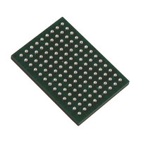
VSC8211XVW Vitesse Semiconductor Corp, VSC8211XVW Datasheet - Page 16

VSC8211XVW
Manufacturer Part Number
VSC8211XVW
Description
IC PHY 10/100/1000 SGL 117-LBGA
Manufacturer
Vitesse Semiconductor Corp
Type
PHY Transceiverr
Specifications of VSC8211XVW
Number Of Drivers/receivers
1/1
Protocol
Gigabit Ethernet
Voltage - Supply
3 V ~ 3.6 V
Mounting Type
Surface Mount
Package / Case
117-LBGA
Case
BGA
Dc
07+
Lead Free Status / RoHS Status
Lead free / RoHS Compliant
Other names
907-1023
Available stocks
Company
Part Number
Manufacturer
Quantity
Price
Company:
Part Number:
VSC8211XVW
Manufacturer:
VITESSE
Quantity:
5
Company:
Part Number:
VSC8211XVW
Manufacturer:
Semtech
Quantity:
3 413
Company:
Part Number:
VSC8211XVW
Manufacturer:
VITESSE
Quantity:
648
Company:
Part Number:
VSC8211XVW
Manufacturer:
Vitesse Semiconductor Corporation
Quantity:
10 000
Part Number:
VSC8211XVW
Manufacturer:
VITESSE
Quantity:
20 000
7 Document History and Notices
VMDS-10105 Revision 4.1
October 2006
Revision
Number
0.1.0
0.1.1
2.0
4.0
4.1
October 2006
August 17 05
Feb. 13 04
May 11 04
July 08 04
Date
First Preliminary Release
Updated pin description with VDD12A and Power supply recommendations.
Added Errata Section.
Updated ‘specification’ section with VDD12A reference.
Updated LED ECO changes.
Added GMII,MII,TBI timing sections
Updated document style to reflect Vitesse corporate standards.
Replaced Errata section with Design Guidelines section.
Added lead-free (Pb-free) package information.
Updated register section.
Added Reset Timing section.
•
•
•
•
•
•
•
•
In the media converter application diagram, the RJ-45 speed was corrected from
10/100/1000BASE-T to 1000BASE-T.
Throughout the datasheet, information was added regarding the 100BASE-FX
mode. The following lists the main information:
– For information about twisted pair signals in 100BASE-FX mode, see
– For information about 100BASE-FX system schematics, see
– For information about 100BASE-FX connections and initialization, see
– For information about 100BASE-FX current consumption, see
In the list of LED function assignments, the function of LED pin 3, value 00, was
corrected from Collision to Link/Activity.
In the listing of JTAG interface instruction codes, the register width given for the
instructions EXTEST and SAMPLE/PRELOAD was corrected from 196 bits to 78
bits.
The MII transmit timing diagram was redrawn to more accurately reflect the delay
from TXCLK to TXD[3:0], TXEN, and TXER. For more information about this
specification, see
In the JTAG interface AC timing diagram, missing labels were added that had been
left out in the prior revision.
In the reset AC timing diagram, the MDIO signal pulse width was widened to be
more accurate relative to the pulse width of the REFCLK signal. For more
information about this specification, see
In the reset AC timing specifications, T
EEPROM is present, an additional 100ms is required. For more information about
reset AC timing, see
“Twisted Pair Interface
Schematic – ‘100Mbps Fiber Media’
11.5: "100Mbps Fiber Support Over Copper Media Interface"
"100BASE-FX Initialization
@ 3.3V, RGMII-100BASE-FX, FDX, 1518 Byte Random data packet, 100%
Utilization, SFP Mode
16 of 165
Figure 39: “MII Transmit AC Timing
Table 73: “RESET AC Timing
Off”.
Signals”.
Script".
Comments
READY
Implementation".
Figure 51: "RESET AC
signal, a condition was added that if
Specification”.
(100Mbps)”.
Timing".
Figure 13: "System
and
Table 43: “VDDIO
Section 33.4:
Datasheet
VSC8211
Table 12:
Section


