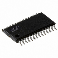
PCA9575PW2,118 NXP Semiconductors, PCA9575PW2,118 Datasheet - Page 9

PCA9575PW2,118
Manufacturer Part Number
PCA9575PW2,118
Description
IC I2C/SMBUS 16BIT GPIO 28-TSSOP
Manufacturer
NXP Semiconductors
Series
-r
Datasheet
1.PCA9575HF118.pdf
(38 pages)
Specifications of PCA9575PW2,118
Interface
I²C, SMBus
Number Of I /o
16
Interrupt Output
Yes
Frequency - Clock
400kHz
Voltage - Supply
1.1 V ~ 3.6 V
Operating Temperature
-40°C ~ 85°C
Mounting Type
Surface Mount
Package / Case
28-TSSOP
Includes
POR
Description/function
16-bit I2C-bus and SMBus
Maximum Operating Temperature
+ 85 C
Minimum Operating Temperature
- 40 C
Mounting Style
SMD/SMT
Supply Voltage (max)
3.6 V
Supply Voltage (min)
1.1 V
Lead Free Status / RoHS Status
Lead free / RoHS Compliant
Other names
935286414118
NXP Semiconductors
Table 3.
PCA9575_3
Product data sheet
Register number
00h
01h
02h
03h
04h
05h
06h
07h
08h
09h
0Ah
0Bh
0Ch
Register summary
7.3 Command register
7.4 Register definitions
D3
0
0
0
0
0
0
0
0
1
1
1
1
1
Following the successful acknowledgement of the slave address + R/W bit, the bus master
will send a byte to the PCA9575, which will be stored in the Command register.
The lowest 4 bits are used as a pointer to determine which register will be accessed. Only
a Command register code with the 4 least significant bits equal to the 16 allowable values
as defined in
command codes will not be acknowledged. At power-up, this register defaults to 00h, with
the AI bit set to logic 0, and the lowest 4 bits set to logic 0.
If the Auto-Increment flag is set (AI = 1), the 4 least significant bits of the Command
register are automatically incremented after a read or write. This allows the user to
program and/or read the 16 command registers (listed in
roll over to register 00h after the last register is accessed and the selected registers will be
overwritten or re-read.
If the Auto-Increment flag is cleared (AI = 0), the 4 least significant bits are not
incremented after data is read or written, only one register will be repeatedly read or
written.
Fig 8.
D2
0
0
0
0
1
1
1
1
0
0
0
0
1
D1
0
0
1
1
0
0
1
1
0
0
1
1
0
Reset state = 00h
Remark: The Command register does not apply to Software Reset I
Command register
Table 3 “Register summary”
D0
0
1
0
1
0
1
0
1
0
1
0
1
0
Name
IN0
IN1
INVRT0
INVRT1
BKEN0
BKEN1
PUPD0
PUPD1
CFG0
CFG1
OUT0
OUT1
MSK0
Rev. 03 — 9 November 2009
16-bit I
Auto-Increment flag
2
C-bus and SMBus, level translating, low voltage GPIO
AI
Type
read only
read only
read/write
read/write
read/write
read/write
read/write
read/write
read/write
read/write
read/write
read/write
read/write
0
0
will be acknowledged. Reserved or undefined
0
D3
Function
Input port 0 register
Input port 1 register
Polarity inversion port 0 register
Polarity inversion port 1 register
Bus-hold enable 0 register
Bus-hold enable 1 register
Pull-up/pull-down selector port 0 register
Pull-up/pull-down selector port 1 register
Configuration port 0 register
Configuration port 1 register
Output port 0 register
Output port 1 register
Interrupt mask port 0 register
register address
D2
D1
002aad568
Table
D0
3) sequentially. It will then
2
C-bus address.
PCA9575
© NXP B.V. 2009. All rights reserved.
9 of 38


