AD9929BBCZ Analog Devices Inc, AD9929BBCZ Datasheet - Page 34
AD9929BBCZ
Manufacturer Part Number
AD9929BBCZ
Description
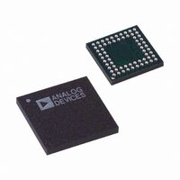
IC CCD SIGNAL PROCESSOR 64-BGA
Manufacturer
Analog Devices Inc
Type
CCD Signal Processor, 12-Bitr
Datasheet
1.AD9929BBCZ.pdf
(64 pages)
Specifications of AD9929BBCZ
Input Type
Logic
Output Type
Logic
Interface
3-Wire Serial
Mounting Type
Surface Mount
Package / Case
64-CSPBGA
Analog Front End Type
CCD
Analog Front End Category
Video
Interface Type
Serial (3-Wire)
Input Voltage Range
0.5V
Operating Supply Voltage (min)
2.7V
Operating Supply Voltage (typ)
3V
Operating Supply Voltage (max)
3.6V
Resolution
12b
Number Of Adc's
1
Power Supply Type
Analog/Digital
Operating Temp Range
-20C to 85C
Operating Temperature Classification
Commercial
Mounting
Surface Mount
Pin Count
64
Package Type
CSPBGA
Number Of Channels
1
Lead Free Status / RoHS Status
Lead free / RoHS Compliant
Current - Supply
-
Lead Free Status / RoHS Status
Compliant, Lead free / RoHS Compliant
Available stocks
Company
Part Number
Manufacturer
Quantity
Price
Company:

Part Number:
AD9929BBCZ
Manufacturer:
ADI
Quantity:
531


AD9929
VERTICAL TIMING GENERATION
The AD9929 provides a very flexible solution for generating
vertical CCD timing and can support multiple CCDs and
different system architectures. The 4-phase vertical transfer
clocks XV1 to XV4 are used to shift each line of pixels into the
horizontal output register of the CCD. The AD9929 vertical
outputs can be individually programmed into four different
vertical pulse patterns identified as VTP0, VTP1, VTP2, and
VTP3. Each vertical pulse pattern is a unique set of precon-
figured XV1 to XV4 sequences. Once the vertical patterns have
been configured using the registers shown in Table 24, pointer
registers are used to select in which region of the CCD a
particular vertical pattern is output. The pointer registers are
described in Table 22.
Up to five unique CCD regions may be specified. Finally, the
readout of the entire field is constructed by combining one or
more of the individual regions sequentially. With up to five
regions available, different steps of the readout such as high
speed line shifts and vertical image transfer can be supported.
CREATING VERTICAL SEQUENCES
Figure 32 through Figure 34 provide an overview of how the
vertical timing is generated in four basic steps.
Step 1: Create the individual pulses for patterns VTP0, VTP1,
VTP2, and VTP3 (see Figure 32).
The registers shown in Table 22 are used to generate the
individual vertical timing pulses, as shown in Figure 32.
The VTPLENx determines the number of pixels between pulse
repetitions. The start polarity (XVxSTARTPOLx) sets the
starting polarity of the vertical sequence and can be program-
med high or low. The first toggle position (XVxTOG1POSx)
and second toggle position (XVxTOG2POSx) are the pixel
locations within the line where the pulse transitions.
Rev. A | Page 34 of 64
Step 2: Create the individual vertical sequences (see Figure 33).
Create the individual vertical sequences by assigning pulse
repetitions to patterns VTP0, VTP1, VTP2, and VTP3 using the
VTPREPx registers as shown in Table 25. The number of repeti-
tions (VTPREPx) determines the number of pulse repetitions
desired within a single line. Programming 1 for VTPREPx gives
a single pulse, and setting to 0 provides a fixed dc output based
on the start polarity value. Figure 33 shows an example of a
VTPx sequence of two VTPx patterns by setting VTPREPx = 2.
Step 3: Output Vertical Sequences into CCD Regions (see
Figure 34).
The AD9929 arranges individual sequences into CCD regions
through the use of sequence pointers (VTPSEQPTRx) and
vertical transfer pattern select (VTPSELx) registers, as described
in Table 23. The VTPSEQPTRx registers are used to point to a
desired VTPSELx register whose value determines what VTPx
pattern is output on the XV1 to XV4 signals. For example, if
VTPSEQPTR0 = 1 and VTPSEL1 = 2, the VTP2 pulse pattern
would output while operating in Region 0 of the CCD.
Step 4: Combining CCD Regions (see Figure 34).
Build the entire field readout by combining multiple regions by
using mode registers SCP0, SCP1, SCP2, SCP3, and SCP4.
The individual CCD regions are combined into a complete field
readout by using sequence change position (SCPx) pointers as
described in Table 23. Figure 34 shows how each field is divided
into multiple regions. This allows the user to change vertical
timing during various stages of the image readout. The boun-
daries of each region are defined by the sequence change
position (SCP). Each SCP is a 8-bit value representing the line
number boundary region. A total of four SCPs allow up to five
different region areas in the field to be defined. The first SCP0 is
always hard-coded to line 0, and the remaining four SCPs are
register programmable.
Related parts for AD9929BBCZ
Image
Part Number
Description
Manufacturer
Datasheet
Request
R


Part Number:
Description:
±1.7g Dual-Axis IMEMS Accelerometer Evaluation Board
Manufacturer:
Analog Devices Inc
Datasheet:

Part Number:
Description:
Inertial Sensor Evaluation System
Manufacturer:
Analog Devices Inc
Datasheet:
Part Number:
Description:
Manufacturer:
Analog Devices Inc
Datasheet:
Part Number:
Description:
Manufacturer:
Analog Devices Inc
Datasheet:
Part Number:
Description:
Manufacturer:
Analog Devices Inc
Datasheet:
Part Number:
Description:
Manufacturer:
Analog Devices Inc
Datasheet:
Part Number:
Description:
Manufacturer:
Analog Devices Inc
Datasheet:
Part Number:
Description:
Manufacturer:
Analog Devices Inc
Datasheet:
Part Number:
Description:
Manufacturer:
Analog Devices Inc
Datasheet:
Part Number:
Description:
Manufacturer:
Analog Devices Inc
Datasheet:
Part Number:
Description:
Manufacturer:
Analog Devices Inc
Datasheet:
Part Number:
Description:
Manufacturer:
Analog Devices Inc
Datasheet: