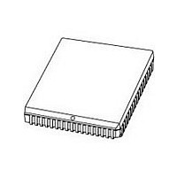
P80C592FFA NXP Semiconductors, P80C592FFA Datasheet - Page 55

P80C592FFA
Manufacturer Part Number
P80C592FFA
Description
Manufacturer
NXP Semiconductors
Datasheet
1.P80C592FFA.pdf
(108 pages)
Specifications of P80C592FFA
Cpu Family
80C
Device Core
80C51
Device Core Size
8b
Frequency (max)
16MHz
Interface Type
CAN/UART
Program Memory Type
ROMLess
Program Memory Size
Not Required
Total Internal Ram Size
512Byte
# I/os (max)
40
Number Of Timers - General Purpose
3
Operating Supply Voltage (typ)
5V
Operating Supply Voltage (max)
5.5V
Operating Supply Voltage (min)
4.5V
On-chip Adc
8-chx10-bit
Instruction Set Architecture
CISC
Operating Temp Range
-40C to 85C
Operating Temperature Classification
Industrial
Mounting
Surface Mount
Pin Count
68
Package Type
PLCC
Lead Free Status / Rohs Status
Compliant
Available stocks
Company
Part Number
Manufacturer
Quantity
Price
Company:
Part Number:
P80C592FFA
Manufacturer:
PANASONIC
Quantity:
1 200
Part Number:
P80C592FFA
Manufacturer:
PHI
Quantity:
20 000
Company:
Part Number:
P80C592FFA/00
Manufacturer:
SYSTECH
Quantity:
40
Part Number:
P80C592FFA/00
Manufacturer:
NXP/恩智浦
Quantity:
20 000
Company:
Part Number:
P80C592FFA/00,512
Manufacturer:
ON
Quantity:
300
Company:
Part Number:
P80C592FFA/00,512
Manufacturer:
NXP Semiconductors
Quantity:
10 000
Company:
Part Number:
P80C592FFA/00,518
Manufacturer:
NXP Semiconductors
Quantity:
10 000
Company:
Part Number:
P80C592FFA/00Ј¬512
Manufacturer:
NXP
Quantity:
702
Philips Semiconductors
13.6.2.4
A CAN-controller, acting as a receiver for certain
information may initiate the transmission of the respective
data by transmitting a Remote Frame to the network,
addressing the data source via the Identifier and setting
the RTR bit HIGH (remote; recessive bus level). If the data
source simultaneously transmits a Data Frame containing
the requested data, it uses the same Identifier. No bus
access conflict occurs due to the RTR bit being set LOW
(data; dominant bus level) in the Data Frame.
13.6.2.5
This field consists of six bits. It includes two reserved bits
(for future expansions of the CAN-protocol), transmitted
with a dominant bus level, and is followed by the Data
Length Code (4 bits).
The number of bytes (destuffed; number of data bytes to
be transmitted/received) in the Data Field is indicated by
the Data Length Code. Admissible values of the Data
Length Code, and hence the number of bytes in the
(destuffed) Data Field, are {0, 1, ...., 8}. A logic 0 (logic 1)
in the Data Length Code is transmitted as dominant
(recessive) bus level, respectively.
13.6.2.6
The data, stored within the Data Field of the Transmit
Buffer, are transmitted according to the Data Length Code.
Conversely, data of a received Data Frame will be stored
in the Data Field of a Receive Buffer. The Data Field can
contain from 0 up to 8 bytes. The most significant bit of the
first data byte (lowest address) is transmitted/received
first.
13.6.2.7
The CRC Field consists of the CRC Sequence (15 bits)
and the CRC Delimiter (1 recessive bit). The Cyclic
Redundancy Code (CRC) encloses the destuffed bit
stream of the Start-Of-Frame, Arbitration Field, Data Field
and CRC Sequence. The most significant bit of the CRC
Sequence is transmitted/received first. This frame check
sequence, implemented in the CAN-controller is derived
from a cyclic redundancy code best suited for frames with
a total bit count of less than 127 bits, see Section 13.6.8.3.
With Start-Of-Frame (dominant bit) included in the code
word, any rotation of the code word can be detected by the
absence of the CRC Delimiter (recessive bit).
1996 Jun 27
8-bit microcontroller with on-chip CAN
RTR bit
Control Field
Data Field
Cyclic Redundancy Code Field (CRC)
55
13.6.2.8
The Acknowledge Field consists of two bits, the
Acknowledge Slot and the Acknowledge Delimiter, which
are transmitted with a recessive level by the transmitter of
the Data Frame. All CAN-controllers having received the
matching CRC Sequence, report this by overwriting the
transmitter's recessive bit in the Acknowledge Slot with a
dominant bit. Thereby a transmitter, still monitoring the bus
level recognizes that at least one receiver within the
network has received a complete and correct message
(i.e. no error was found). The Acknowledge Delimiter
(recessive bit) is the second bit of the Acknowledge Field.
As a result, the Acknowledge Slot is surrounded by two
recessive bits: the CRC Delimiter and the Acknowledge
Delimiter.
All nodes within a CAN network may use all the information
coming to the network by all CAN-controllers (shared
memory concept). Therefore, acknowledgement and error
handling are defined to provide all information in a
consistent way throughout this shared memory. Hence,
there is no reason to discriminate different receivers of a
message in the acknowledge field. If a node is
disconnected from the network due to bus failure, this
particular node is no longer part of the shared memory. To
identify a ‘lost node’ additional and application specific
precautions are required.
13.6.2.9
Each Data Frame or Remote Frame is delimited by the
End-Of-Frame bit sequence which consists of seven
recessive bits (exceeds the bit stuff width by two bits).
Using this method a receiver detects the end of a frame
independent of a previous transmission error because the
receiver expects all bits up to the end of the CRC
Sequence to be coded by the method of bit-stuffing, see
Section 13.6.7.3. The bit-stuffing logic is deactivated
during the End-Of-Frame sequence.
Acknowledge Field (ACK)
End-Of-Frame
Product specification
P8xC592


