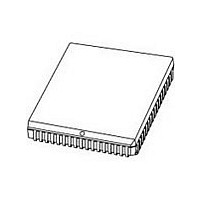
P80C592FFA NXP Semiconductors, P80C592FFA Datasheet - Page 58

P80C592FFA
Manufacturer Part Number
P80C592FFA
Description
Manufacturer
NXP Semiconductors
Datasheet
1.P80C592FFA.pdf
(108 pages)
Specifications of P80C592FFA
Cpu Family
80C
Device Core
80C51
Device Core Size
8b
Frequency (max)
16MHz
Interface Type
CAN/UART
Program Memory Type
ROMLess
Program Memory Size
Not Required
Total Internal Ram Size
512Byte
# I/os (max)
40
Number Of Timers - General Purpose
3
Operating Supply Voltage (typ)
5V
Operating Supply Voltage (max)
5.5V
Operating Supply Voltage (min)
4.5V
On-chip Adc
8-chx10-bit
Instruction Set Architecture
CISC
Operating Temp Range
-40C to 85C
Operating Temperature Classification
Industrial
Mounting
Surface Mount
Pin Count
68
Package Type
PLCC
Lead Free Status / Rohs Status
Compliant
Available stocks
Company
Part Number
Manufacturer
Quantity
Price
Company:
Part Number:
P80C592FFA
Manufacturer:
PANASONIC
Quantity:
1 200
Part Number:
P80C592FFA
Manufacturer:
PHI
Quantity:
20 000
Company:
Part Number:
P80C592FFA/00
Manufacturer:
SYSTECH
Quantity:
40
Part Number:
P80C592FFA/00
Manufacturer:
NXP/恩智浦
Quantity:
20 000
Company:
Part Number:
P80C592FFA/00,512
Manufacturer:
ON
Quantity:
300
Company:
Part Number:
P80C592FFA/00,512
Manufacturer:
NXP Semiconductors
Quantity:
10 000
Company:
Part Number:
P80C592FFA/00,518
Manufacturer:
NXP Semiconductors
Quantity:
10 000
Company:
Part Number:
P80C592FFA/00Ј¬512
Manufacturer:
NXP
Quantity:
702
Philips Semiconductors
13.6.5
The Overload Frame consists of two fields:
The transmission of an Overload Frame may only start:
The P8xC592's on-chip CAN-controller will never initiate
transmission of a condition 1 Overload Frame and will only
react on a transmitted condition 2 Overload Frame,
according to the CAN-protocol. No more than two
Overload Frames are generated to delay a Data Frame or
a Remote Frame. Although the overall form of the
Overload Frame corresponds to that of the Error Frame,
an Overload Frame does not initiate or require the
retransmission of the preceding frame.
1996 Jun 27
handbook, full pagewidth
The Overload Flag
The Overload Delimiter.
Condition 1; during the first bit period of an expected
Intermission Field.
Condition 2; one bit period after detecting the dominant
bit during Intermission Field.
8-bit microcontroller with on-chip CAN
O
VERLOAD
DATA FRAME
F
RAME
1 ERROR
superimposing of
FLAG
ERROR FLAGs
Fig.20 Error Frame.
ERROR FRAME
58
13.6.5.1
The Overload Flag consists of six dominant bits and has a
similar format to the Error Flag.
There are two conditions in the CAN-protocol which lead
to the transmission of an Overload Flag:
The Overload Flag's form corrupts the fixed form of the
Intermission Field. All other CAN-controllers detecting the
overload condition also transmit an Overload Flag
(condition 2).
Condition 1; receiver circuitry requires more time to
process the current data before receiving the next frame
(receiver not ready).
Condition 2; detection of a dominant bit during
Intermission Field (see Section 13.6.6).
ERROR DELIMITER
Overload Flag
MGA165
INTER-FRAME SPACE
or OVERLOAD FRAME
Product specification
P8xC592


