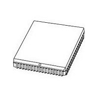
P80C592FFA NXP Semiconductors, P80C592FFA Datasheet - Page 63

P80C592FFA
Manufacturer Part Number
P80C592FFA
Description
Manufacturer
NXP Semiconductors
Datasheet
1.P80C592FFA.pdf
(108 pages)
Specifications of P80C592FFA
Cpu Family
80C
Device Core
80C51
Device Core Size
8b
Frequency (max)
16MHz
Interface Type
CAN/UART
Program Memory Type
ROMLess
Program Memory Size
Not Required
Total Internal Ram Size
512Byte
# I/os (max)
40
Number Of Timers - General Purpose
3
Operating Supply Voltage (typ)
5V
Operating Supply Voltage (max)
5.5V
Operating Supply Voltage (min)
4.5V
On-chip Adc
8-chx10-bit
Instruction Set Architecture
CISC
Operating Temp Range
-40C to 85C
Operating Temperature Classification
Industrial
Mounting
Surface Mount
Pin Count
68
Package Type
PLCC
Lead Free Status / Rohs Status
Compliant
Available stocks
Company
Part Number
Manufacturer
Quantity
Price
Company:
Part Number:
P80C592FFA
Manufacturer:
PANASONIC
Quantity:
1 200
Part Number:
P80C592FFA
Manufacturer:
PHI
Quantity:
20 000
Company:
Part Number:
P80C592FFA/00
Manufacturer:
SYSTECH
Quantity:
40
Part Number:
P80C592FFA/00
Manufacturer:
NXP/恩智浦
Quantity:
20 000
Company:
Part Number:
P80C592FFA/00,512
Manufacturer:
ON
Quantity:
300
Company:
Part Number:
P80C592FFA/00,512
Manufacturer:
NXP Semiconductors
Quantity:
10 000
Company:
Part Number:
P80C592FFA/00,518
Manufacturer:
NXP Semiconductors
Quantity:
10 000
Company:
Part Number:
P80C592FFA/00Ј¬512
Manufacturer:
NXP
Quantity:
702
Philips Semiconductors
14 INTERRUPT SYSTEM
External events and the real-time-driven on-chip
peripherals require service by the CPU asynchronous to
the execution of any particular section of code. To tie the
asynchronous activities of these functions to normal
program execution a multiple-source, two-priority-level,
nested interrupt system is provided. Interrupt response
latency is from 2.25 s to 7.5 s when using a 16 MHz
crystal. The latency time strongly depends on the
sequence of instructions executed directly after an
interrupt request. During a CAN-DMA transfer the interrupt
system is disabled (see Section 13.5.17). The P8xC592
acknowledges interrupt requests from fifteen sources as
follows:
Each interrupt vectors to a separate location in Program
Memory for its service program. Each source can be
individually enabled or disabled by a corresponding bit in
the IEN0 or IEN1 register, moreover each interrupt may be
programmed to a HIGH or LOW priority level using a
corresponding bit in the IP0 or IP1 register. Also all
enabled sources can be globally disabled or enabled. Both
external interrupts can be programmed to be
level-activated or transition-activated, and an active LOW
level allows ‘wire-ORing’ of several interrupt sources to the
input pin.
1996 Jun 27
INT0 and INT1: externally via pins 27 and 28
respectively
Timer 0 and Timer 1: from the two internal counters
– If the capture function remains unused and the
Timer T2, 8 separate interrupts:
– 4 capture interrupts
– 3 compare interrupts
– an overflow interrupt
ADC end-of-conversion interrupt
CAN-controller interrupt
UART serial I/O port interrupt.
8-bit microcontroller with on-chip CAN
Capture Register contents are ‘don't care’ then the
corresponding input pins ‘CTnI’, with ‘n = 0 ... 3’, may
be used as positive and/or negative edge triggered
external interrupts INT2 to INT5. But note that they
can not terminate the Idle mode because the Timer 2
is switched off then
63
Product specification
P8xC592


