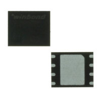
W25X40BVZPIG Winbond Electronics, W25X40BVZPIG Datasheet - Page 24

W25X40BVZPIG
Manufacturer Part Number
W25X40BVZPIG
Description
IC SPI FLASH 4MBIT 8WSON
Manufacturer
Winbond Electronics
Datasheet
1.W25X40BVSNIG.pdf
(51 pages)
Specifications of W25X40BVZPIG
Format - Memory
FLASH
Memory Type
FLASH
Memory Size
4M (512K x 8)
Speed
104MHz
Interface
SPI Serial
Voltage - Supply
2.7 V ~ 3.6 V
Operating Temperature
-40°C ~ 85°C
Package / Case
8-WSON
Lead Free Status / RoHS Status
Lead free / RoHS Compliant
Available stocks
Company
Part Number
Manufacturer
Quantity
Price
9.2.11
The “Continuous Read Mode” bits are used in conjunction with the “Fast Read Dual I/O” instruction to
provide the highest random Flash memory access rate with minimum SPI instruction overhead, thus
allow true XIP (execute in place) to be performed on serial flash devices.
M7-0 need to be set by the Dual I/O Read instruction. M5-4 are used to control whether the 8-bit SPI
instruction code BBh is needed or not for the next command. When M5-4 = (1,0), the next command
will be treated same as the current Dual I/O Read command without needing the 8-bit instruction
code; when M5-4 do not equal to (1,0), the device returns to normal SPI mode, all commands can be
accepted. M7-6 and M3-0 are reserved bits for future use, either 0 or 1 values can be used.
9.2.12
Continuous Read Mode Reset instruction can be used to set M4 = 1, thus the device will release the
Continuous Read Mode and return to normal SPI operation, as shown in figure 12.
Since W25X10BV/20BV/40BV does not have a hardware Reset pin, so if the controller resets while
W25X10BV/20BV/40BV are set to Continuous Mode Read, the W25X10BV/20BV/40BV will
not recognize any initial standard SPI instructions from the controller. To address this possibility, it is
recommended to issue a Continuous Read Mode Reset instruction as the first instruction after a
system Reset. Doing so will release the device from the Continuous Read Mode and allow Standard
SPI instructions to be recognized.
To reset “Continuous Read Mode” during Dual I/O operation, sixteen clocks are needed to shift in
instruction “FFFFh”.
/CS
/CS
CLK
CLK
IO
IO
IO
IO
0
0
1 1
Continuous Read Mode Bits (M7-0)
Continuous Read Mode Reset (FFFFh)
Mode 3
Mode 3
Mode 0
Mode 0
Figure 12. Continuous Read Mode Reset for Fast Read Dual I/O
0
1
2
3
4
5
- 24 -
6
Mode Bit Reset
Don’t Care
Don’t Care
for Dual I/O
FFFFh
7
8
W25X10BV/20BV/40BV
9
10
11
12
13
14
15
Mode 3
Mode 0


