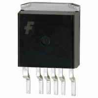
FSCM0465RJ Fairchild Semiconductor, FSCM0465RJ Datasheet - Page 10

FSCM0465RJ
Manufacturer Part Number
FSCM0465RJ
Description
IC SWIT PWM GREEN OVP HV D2PAK
Manufacturer
Fairchild Semiconductor
Datasheet
1.FSCM0465RJX.pdf
(20 pages)
Specifications of FSCM0465RJ
Output Isolation
Isolated
Frequency Range
60 ~ 72kHz
Voltage - Input
8 ~ 20 V
Voltage - Output
650V
Power (watts)
55W
Operating Temperature
25°C ~ 150°C
Package / Case
TO-263-7, D²Pak (6 leads + Tab), TO-263CB
Power Switch Family
FSCM0465R
Input Voltage
85 to 265V
Power Switch On Resistance
2.2Ohm
Output Current
2.3A
Number Of Outputs
Single
Mounting
Surface Mount
Supply Current
2.5mA
Package Type
D2PAK
Operating Temperature (min)
-25C
Operating Temperature (max)
85C
Operating Temperature Classification
Commercial
Pin Count
5 +Tab
Power Dissipation
140W
Lead Free Status / RoHS Status
Lead free / RoHS Compliant
FSCM0465R Rev. 1.0.1
© 2006 Fairchild Semiconductor Corporation
Functional Description
1. Startup : Figure 16 shows the typical startup circuit
and transformer auxiliary winding for the FSCM0465R
application. Before the FSCM0465R begins switching, it
consumes only startup current (typically 20µA) and the
current supplied from the DC link supply current
consumed by the FPS (I
capacitor (C
reaches start voltage of 12V (V
begins switching and the current consumed by the
FSCM0465R increases to 2.5mA. Then the FSCM0465R
continues its normal switching operation and the power
required for this device is supplied from the transformer
auxiliary winding, unless V
voltage of 8V (V
of the control IC, V
with 4V hysteresis. Figure 17 shows the relationship
between the current consumed by the FPS (I
supply voltage (V
FSCM0465R Rev. 00
25μA
3mA
I
CC
Figure 17. Relation Between Operating Supply
FSCM0465R Rev. 00
(V
line
min
AC line
Power Down
- V
a
line
) connected to the V
Figure 16. Startup Circuit
max
Current and V
STOP
CC
Vstop=8V
)
CC
FSCM0465R
).
). To guarantee the stable operation
has under-voltage lockout (UVLO)
CC
Vstart=12V
) and charges the external
CC
CC
START
drops below the stop
Voltage
I
V
SUP
I
Power Up
CC
CC
CC
), the FSCM0465R
C
Ca
pin. When V
Rstr
DC
Vz
CC
Da
) and the
V
CC
CC
10
The minimum current supplied through the startup
resistor is given by:
where V
start voltage (12V) and R
startup resistor should be chosen so that I
than the maximum startup current (40µA). If not, V
not be charged to the start voltage and FPS fails to start.
2. Feedback Control : The FSCM0465R employs
current mode control, as shown in Figure 18. An opto-
coupler (such as the H11A817A) and a shunt regulator
(such as the KA431) are typically used to implement the
feedback network. Comparing the feedback voltage with
the voltage across the Rsense resistor makes it possible
to control the switching duty cycle. When the reference
pin voltage of the KA431 exceeds the internal reference
voltage of 2.5V, the H11A817A LED current increases,
pulling down the feedback voltage and reducing the duty
cycle. This event typically happens when the input
voltage is increased or the output load is decreased.
2.1 Pulse-by-pulse Current Limit : Because current
mode control is employed, the peak current through the
SenseFET is determined by the inverting input of the
PWM comparator (Vfb*) as shown in Figure 18. When
the current through the opto-transistor is zero and the
current limit pin (#5) is left floating, the feedback current
source (I
resistor (R+2.5R=2.8k). In this case, the cathode voltage
of diode D2 and the peak drain current have maximum
values of 2.5V and 2.5A, respectively. The pulse-by-
pulse current limit can be adjusted using a resistor to
GND on the current limit pin (#5). The current limit level
using an external resistor (R
Figure 18. Pulse Width Modulation (PWM) Circuit
Vo
FSCM0465R Rev. 00
line
FB
H11A817A
KA431
min
) of 0.9mA flows only through the internal
I
sup
Vfb
is the minimum input voltage, V
R
min
LI M
C
=
I
B
LIM
(
6
4
I
delay
V
2
=
Vcc
SD
⋅
2.8
V
0.3k
D1
R
line
str
Vref
LIM
K
min
LIM
Ω +
I
V
is the startup resistor. The
FB
D2
+
⋅
fb
-
*
2.5
−
0.9mA
) is given by:
R
V
2.5R
R
star t
A
LIM
OSC
)
⋅
OLP
R
1
str
sup
driver
Gate
www.fairchildsemi.com
min
R
start
sense
SenseFET
is larger
CC
is the
can
(1)
(2)


