OM6277,598 NXP Semiconductors, OM6277,598 Datasheet
OM6277,598
Specifications of OM6277,598
935283226598


Related parts for OM6277,598


OM6277,598 Summary of contents
Page 1
Abstract PCA9564 evaluation board description, features and operation modes are discussed. Source code in C language, containing communication routines between an 80C51-core microcontroller and the PCA9564 is provided. AN10149 PCA9564 Evaluation Board Jean-Marc Irazabal PCA Technical Marketing Manager Paul Boogaards ...
Page 2
TABLE OF CONTENTS OVERVIEW...........................................................................................................................................................................................3 D ........................................................................................................................................................................................3 ESCRIPTION O ......................................................................................................................................................................4 RDERING INFORMATION TECHNICAL INFORMATION – HARDWARE ...............................................................................................................................4 B ..................................................................................................................................................................................4 LOCK DIAGRAM .........................................................................................................................................................................4 DEVICE ADDRESSES S ..........................................................................................................................................................................................5 CHEMATIC PCA9564 VALUATION OARD OP VIEW J H ........................................................................................................................................................................6 ...
Page 3
OVERVIEW Description The PCA9564 Evaluation Board demonstrates the Philips PCA9564 I master (connected to its parallel bus and its control signals) and any master and slave devices connected to its I The evaluation board is populated with the following devices ...
Page 4
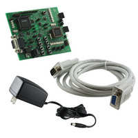
Ordering information The complete PCA9564 evaluation board Kit consists of the: • PCA9564 evaluation board • power supply • DB-9 connector Kit can be obtained through your local Philips Semiconductors Sales organization. It can also be obtained ...
Page 5
Schematic Figure 2. PCA9564 Evaluation Board Schematic 5 ...
Page 6
PCA9564 Evaluation Board Top view VDDMCU + PORT1LV51 LD9 to LD12 (top to bottom) P89LV51RD2 JP12 – SCLLV JP13 – SDALV JP9 – PSEN\ SP3223 JP11 JP17 JP18 Figure 3. PCA9564 Evaluation Board Top View Jumpers and Headers Label Purpose ...
Page 7
JP6 Connect I C-bus 1 and 2 (I2C I C-bus 2 Connect) 2 JP7 Connect I C-bus 1 and 2 I C-bus 2 (I2C Connect) JP8 Power supply for the 2 (VDD Conn) I C-bus connectors JP9 89C51Rx+/Rx2/66x (PSEN\) ...
Page 8
Pushbuttons – User interface and Reset • Pushbuttons S1 to S8: They are connected to the 8 inputs of the PCA9554A interface between the user and the microcontroller(s) to perform actions such as program selection, user definable events ...
Page 9
ISP programming for both devices can be done using Flash Magic. Flash Magic is a free, powerful, feature-rich Windows application that allows easy programming of Philips Flash microcontrollers. Flash Magic uses Intel Hex files as input to program the targeted ...
Page 10
Use of other 80C51 type Philips microcontrollers Any Philips 80C51 microcontroller pin to pin compatible with the P89LV51Rx2 device can be used as to interface with the PCA9564. • Power supply: It can be chosen from: - The internal 3.3 ...
Page 11
P89LV51 RxD pin can be connected to the P89LPC932 TxD pin through jumper JP18 - JP18 open: pins are not connected together - JP18 closed: pins are connected together Note: Jumpers JP2 and JP3 must be open when JP17 and ...
Page 12
TECHNICAL INFORMATION – EMBEDDED FIRMWARE Overview PCA9564 evaluation board is delivered with 4 different embedded firmware programs (Program 1 to Program 4) allowing the user to run simple applications in order to evaluate the PCA9564’s capabilities, to monitor data and ...
Page 13
LD12 provides the following information: LD12 = OFF → Scan of the EEPROM not performed - LD12 = ON → Scan of the EEPROM performed - LD13 to LD20 display the number of the pattern currently selected. COMMAND 1.1 COMMAND ...
Page 14
Program 4 (LD9 = ON, LD10 = ON): I Program 4 uses the P89LV51RD2/PCA9564 slave. In this mode, the PCA9564 searches for the P89LPC932’s I the 3 LSB’s of the P89LPC932 I ...
Page 15
Program 1: P89LV51RD2–PCA9564–PCA9531; PCA9531 dynamic programming PUSHBUTTONS S1 S5 PSC PSC - + S2 S6 PWM PWM - + S3 S7 BR0 OFF BR1 BRx S4 S8 INIT CHGE PRG Figure 6. Program 1 – PCA9531 dynamic programming LD1 to ...
Page 16
Program 2: P89LV51RD2–PCA9564–PCA9531–PCF85116–P89LPC932; Predefined blinking patterns PUSHBUTTONS S1 S5 NOT PRG USED CHGE S2 S6 NOT NOT USED USED S3 S7 NOT NOT USED USED CHGE CHK PRG Figure 7. Program 2 – Preprogrammed blinking patterns Program ...
Page 17
Program 4: P89LV51RD2–PCA9564–PCA9531–P89LPC932; I LD1 to LD8 = OFF LD13 to LD20 = OFF LD11 = OFF, LD12 = OFF I2C_Address = 0x00 S1 pushed pushed? YES LD11 = OFF, LD12 = OFF Switch off LED[13:20]: S ...
Page 18
Source Code P89LV51RD2 – Rev 1.0 P89LV51RD2/PCA9564 source code of the embedded software is organized in several files written in C language. Modularity of the files allows building applications using an 8051-core microcontroller and a PCA9564 in an easy and ...
Page 19
Contains the source code of the I 3. ua_exprt.h: Contains the definition of variables used in the I Complete source code can be found in Appendix 2 “P89LPC932 Microcontroller Source Code – Rev1.0”. Download software, programs and documentation ...
Page 20
Appendix 1: P89LV51RD2 Microcontroller Source Code – Rev 1.0 I2CEXPRT.H //************************************************************************* // // COPYRIGHT (c) 2003 BY PHILIPS SEMICONDUCTORS // -- ALL RIGHTS RESERVED // // File Name: i2cexpert.h // Created: ...
Page 21
I2C_WriteRepRead(I2C_MESSAGE *msg1, I2C_MESSAGE *msg2); extern void I2C_Read(I2C_MESSAGE *msg); extern void I2C_ReadRepRead(I2C_MESSAGE *msg1, I2C_MESSAGE *msg2); extern void I2C_ReadRepWrite(I2C_MESSAGE *msg1, I2C_MESSAGE *msg2); extern void Blinker_Up_Down(void); extern void LV51_LPC932(void); extern void ReadEEprom(short int MinEEPtr, short int MaxEEPtr, int Operation_EEprom, int Operation_Function); ...
Page 22
Buffer1[5] = 0x00; Buffer1[6] = 0x00; I2C_Write(&Message1); Message2.address = PCA9554_WR; Message2.buf = Buffer2; Message2.nrBytes = 1; Buffer2[ Message3.address = PCA9554_RD; Message3.buf = Buffer3; Message3.nrBytes = 1; } //**************************************************************************** // Delay time in milliseconds // Insert a wait into ...
Page 23
Main program //**************************************************************************** void main(void) { Init_PCA9564(); Init_Slaves(); Init_LPC932(); LED0 = 0; LED1 = 0; LED2 = 0; LED3 = 0; while (1) { GPIO_Interrupt_Handler(); Program_Selection(); } } I2C_Routines.h //************************************************************************* // // ...
Page 24
CRX; extern idata BYTE Buffer1[32]; extern idata BYTE Buffer2[32]; extern idata BYTE Buffer3[16]; extern idata BYTE Buffer4[16]; extern idata I2C_MESSAGE Message1; extern idata I2C_MESSAGE Message2; extern idata I2C_MESSAGE Message3; extern idata I2C_MESSAGE Message4; //**************************************************************************** // I2C Address ...
Page 25
Search_Successful = 0; } break; case 0x20 : // no Ack received PCA9564_Write(I2CCON,0xD0 | CRX); break; } Address_Sent_Status = 0x00; Command_Sent_Status = 0x00; } return I2C_Address_Write; } //**************************************************************************** // GPIO Interrupt Handling function // One shot mode ...
Page 26
Message1.nrBytes = 7; Buffer1[0] = 0x11; Buffer1[1] = 0x80; Buffer1[2] = 0x80; Buffer1[3] = 0x80; Buffer1[4] = 0x80; Buffer1[5] = 0xAA; Buffer1[6] = 0xFF; I2C_Write(&Message1); Frequency_0 = Buffer1[1]; DutyCycle_0 = Buffer1[2]; Frequency_1 = Buffer1[3]; DutyCycle_1 = Buffer1[4]; while (Buffer3[0]!=0x7F) { ...
Page 27
LED3 = 1; if (BR_Select == 0 & Frequency_0 < 0xFF) { Buffer1[0] = 0x01; Frequency_0++; Buffer1[1] = Frequency_0; I2C_Write(&Message1); Buffer3[0] = 0xFF (BR_Select == 1 & Frequency_1 < 0xFF) { Buffer1[0] = 0x03; Frequency_1++; ...
Page 28
I2C_Write(&Message1); Buffer3[0] = 0xFF; BR_Select = 0; LED2 = 1; break Message1.nrBytes = 3; Buffer1[0] = 0x15; // subaddress = 0x15 Buffer1[1] = 0x00; // PCA9531 all LEDs off when leaving Program 1 Buffer1[2] = 0x00; I2C_Write(&Message1); ...
Page 29
We're going to write one byte (subaddress) if (Operation_EEprom == 0) { EEPROM_Scan_Done = 0; Message4.nrBytes = 2; I2C_Write(&Message3); InsertDelay(2); I2C_Read(&Message4); switch (Buffer4[1]) { case 0x00 : if (MinPtrFound_0 == 0) { MinPtr_0 = NextEEaddress; MinPtrFound_0 = 1; } ...
Page 30
Message1.address = Buffer4[3]; Message1.nrBytes = Buffer4[ Message1.buf I2C_Write(&Message1); InsertDelay(Buffer4[2]); break; case 0x01 : break; case 0x02 : break NextEEaddress = NextEEaddress + Buffer4[0]; GPIO_Interrupt_Handler(); // Check if an action on S8 ...
Page 31
I2C_Write(&Message1); Buffer4[0] = 0x00; Buffer4[1] = 0xFF; I2C_Write(&Message4); } //**************************************************************************** // Program 3 : P89LV51 <--> PCA9564 <--> P89LPC932 // Through Pushbuttons, Byte to be sent to LPC932 can be programmed // Once done, a pushbutton sends the LPC932 I2C ...
Page 32
I2C_Write(&Message1); DataByteLPC932 = 0xFF; Buffer4[0] = 0x00; Buffer4[1] = DataByteLPC932; I2C_Write(&Message4); Buffer3[0] = 0xFF; break; case 0xEF : if (BitCounter < BitCounter++; } else { BitCounter = 1; } Buffer3[0] = 0xFF; break; case 0xFE : if (BitCounter ...
Page 33
LS0_4 = 0; LS0_5 = 0; DataByteLPC932_2 = 1; ValueToBeChanged = 0; } else { LS0_4 = 1; LS0_5 = 0; DataByteLPC932_2 = 0; ValueToBeChanged = 0; ...
Page 34
ValueToBeChanged = 0; } Message1.nrBytes = 2; Buffer1[0] = 0x16; Buffer1[1] = LS1; I2C_Write(&Message1); } break; case (ValueToBeChanged == (DataByteLPC932_6 == 0) { LS1_4 = 0; LS1_5 = 0; DataByteLPC932_6 = 1; ValueToBeChanged = ...
Page 35
Program 4:P89LV51 <--> PCA9564 <--> P89LPC932 // Initiates an automatic I2C slave address search in order // to find P89LPC932's I2C slave address //**************************************************************************** void I2C_Address_Search(void) { bdata BYTE I2C_Address; LED2 = 1; LED3 = 1; while (Buffer3[0]!=0x7F) ...
Page 36
I2CDRIVR.H //************************************************************************* // // COPYRIGHT (c) 2003 BY PHILIPS SEMICONDUCTORS // -- ALL RIGHTS RESERVED // // File Name: i2cdriver.h // Created: June 2, 2003 // Modified: June 9, 2003 // ...
Page 37
Input(s): none. * Output(s): none. * Returns: none. * Description: ERROR: Master or slave handler called while not initialized ***************************************************************************/ static void NoInitErrorProc(void) { PCA9564_Write(I2CCON, 0x40); } /*************************************************************************** * Input(s): none. * Output(s): none. * Returns: none. ...
Page 38
I2CMASTR.C //************************************************************************* // // COPYRIGHT (c) 2003 BY PHILIPS SEMICONDUCTORS // -- ALL RIGHTS RESERVED // // File Name: i2cmaster.c // Created: June 2, 2003 // Modified: June 10, 2003 // ...
Page 39
Ack received PCA9564_Write(I2CCON,0xD0 | CRX); drvStatus = I2C_ERROR; break; case 0x28 : // ack received if (dataCount < msg->nrBytes) { PCA9564_Write(I2CDAT,msg->buf[dataCount++]); PCA9564_Write(I2CCON,0xC0 | CRX); } else { if (msgCount < tfr->nrMessages) { dataCount = 0; ...
Page 40
Input(s): p address of I2C transfer parameter block. * proc procedure to call when transfer completed, * with the driver status passed as parameter. * Output(s): None. * Returns: None. * Description: Start an I2C transfer, containing 1 ...
Page 41
I2CINTFC.C //************************************************************************* // // COPYRIGHT (c) 2003 BY PHILIPS SEMICONDUCTORS // -- ALL RIGHTS RESERVED // // File Name: i2cintfc.c // Created: June 2, 2003 // Modified: June 10, 2003 // ...
Page 42
Input(s): msg I2C message * Returns: None. * Description: Read a message from a slave device. * PROTOCOL: <S><SlvA><R><A><D1><A> ... <Dnum><N><P> ***************************************************************************/ void I2C_Read(I2C_MESSAGE *msg) { iicTfr.nrMessages = 1; iicTfr.p_message = p_iicMsg; p_iicMsg[0] = msg; StartTransfer(); } /*************************************************************************** ...
Page 43
PCA9564sys.h //************************************************************************* // // COPYRIGHT (c) 2003 BY PHILIPS SEMICONDUCTORS // -- ALL RIGHTS RESERVED // // File Name: PCA9564sys.h // Created: June 2, 2003 // Modified: June 4, 2003 // ...
Page 44
PCA9564_Read(unsigned char Reg) { unsigned char RegData; int Reg & 0x01 Reg & 0x02; AUXR = 0x02; for (i=0;i<10;i++); RegData = *((unsigned char pdata *)MCU_COMMAND); AUXR = 0x00; return RegData; } Interrupts.c //************************************************************************* ...
Page 45
Appendix 2: P89LPC932 Microcontroller Source Code – Rev 1.0 Main.c //*************************************************************************** //* main.c //* Date : July 2003 //* Discription : Using I2Cslave code to interact with the //* PCA9564 on the I2C-bus //*************************************************************************** #include <Reg932.h> #include "ua_exprt.h" //*************************************************************************** //* ...
Page 46
Name of module: I2CSLAVE.C /* Creation date: 12 March 2003 /* Program language : (C) Copyright 2003 Philips Semiconductors B.V. /* /************************************************************** #include <Reg932.H> #include "ua_exprt.h" typedef unsigned char BYTE; typedef unsigned short WORD; ...
Page 47
I2C_Init(BYTE *buf, BYTE size) void I2C_Init(void) { unsigned char temp; slaveStatus = SLAVE_IDLE; slaveBuf[0] = 0xA5; slaveBuf[1] = 0x55; slaveBuf[2] = 0x99; size = 3; P1M1 |= 0x0C; P1M2 |= 0x0C; //***************************************************************************** //* Modified ...
Page 48
Copyright 1993 Philips Semiconductors B.V. /* /**************************************************************************** /* /* Description This module consists a number of exported declarations of the I2C /* driver package. Include this module in your source file if you ...
Page 49
Appendix 3: PCA9564 evaluation Board Bill Of Material Part Value C1 100 nF C2 100 nF C3 100 nF C4 100 nF C5 100 nF C6 100 nF 1 µ 100 nF C9 100 nF C10 100 nF ...
Page 50
Part Value 270 Ω R10 270 Ω R11 270 Ω R12 R13 10 kΩ 270 Ω R14 270 Ω R15 270 Ω R16 270 Ω R17 270 Ω R18 270 Ω R19 270 Ω R20 270 Ω R21 R22 10 ...
Page 51
REVISION HISTORY Revision Date _2 20040819 _1 20031211 Description Application note (9397 750 13956). Modifications: - Added “PCA9564 evaluation board web page” paragraph - Replaced www.philipslogic.com Application note, initial version (9397 750 12508 www.standardproducts.philips.com ...
Page 52
Purchase of Philips I patent to use the components in the I conforms to the I be ordered using the code 9398 393 40011. Disclaimers Application information – Applications that are described herein for any of these products are for ...