OM6277,598 NXP Semiconductors, OM6277,598 Datasheet - Page 12
OM6277,598
Manufacturer Part Number
OM6277,598
Description
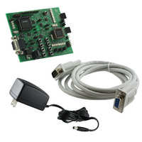
DEMO BOARD FOR PCA9564
Manufacturer
NXP Semiconductors
Datasheet
1.OM6277598.pdf
(52 pages)
Specifications of OM6277,598
Main Purpose
Interface, I2C Controller
Embedded
Yes, MCU, 8-Bit
Utilized Ic / Part
PCA9564
Primary Attributes
I2C Bus Controller, 1 8-Bit GPIO, 1 8-Bit LED Dimmer
Secondary Attributes
8 Momentary Switches, 23 LEDs
Lead Free Status / RoHS Status
Not applicable / Not applicable
Other names
568-4001
935283226598
935283226598


TECHNICAL INFORMATION – EMBEDDED FIRMWARE
Overview
PCA9564 evaluation board is delivered with 4 different embedded firmware programs (Program 1 to Program 4)
allowing the user to run simple applications in order to evaluate the PCA9564’s capabilities, to monitor data and control
signals with the P89LV51RD2 master, and the I
Besides the external power supply, no external hardware or software is required to run those applications. Embedded
programs are erased as soon as the microcontroller is reprogrammed with a different code. The embedded programs
require programming of both P89LV51RD2 and P89LPC932 and “Hex” files can be downloaded from
www.standardproducts.philips.com
with Flash Magic software. For more information about ISP mode and file downloading, refer to the paragraphs “In-
System Programming mode” and “Download software, programs and documentation”.
•
•
-
-
-
Pushbuttons S1 to S8 allow program selection (S8) and initiate specific actions for each program (S1 to S7).
PCA9554A is used to collect actions performed on the pushbuttons and inform the P89LV51RD2 that a reading
routine to determine the nature of the action is requested. Pushing S8 does jump from one program to another (from
Program 1 to Program 4, then again Program 1…).
LD9 and LD10 display the number of the selected program
LD11 and LD12 display program specific information
Program 1 (LD9 = OFF, LD10 = OFF): PCA9531 dynamic programming
Program 1 uses the P89LV51RD2/PCA9564 as an I
dynamically change blinking rates and output states.
LD1 to LD4 are programmed to blink at Blinking rate 0 (BR0), while LD5 to LD8 are programmed to blink at
Blinking Rate 1 (BR1).
Actions on the pushbuttons:
-
-
-
-
-
-
-
-
LD11 and LD12 provide the following information:
-
-
-
-
Program 2 (LD9 = ON, LD10 = OFF): Preprogrammed blinking patterns
Program 2 uses the P89LV51RD2/PCA9564 as an I
the P89LPC932 (with LD13 to LD20) as I
EEPROM.
For a specific selected pattern:
a) Data used to program the PCA9531is read from the EEPROM. Data organization is shown in Figure 4.
b) The PCA9531 is then programmed with the data previously read.
Action on the pushbuttons:
-
-
-
S1: Decrease blinking frequency for both BR0 and BR1 (single shot or permanent push modes)
S2: Decrease duty cycle for both BR0 and BR1 (single shot or permanent push modes)
S3: Select the Blinking Rate (BR0 or BR1) to be programmed through S1, S2, S5, S6 and S7
S4: Reset the programming and program the LEDs to their default blinking frequency
S5: Increase blinking frequency for both BR0 and BR1 (single shot or permanent push modes)
S6: Increase duty cycle for both BR0 and BR1 (single shot or permanent push modes)
S7: Program the LEDs to be OFF or blinking at BR0 or BR1
S8: Jump to the next program (Program 2)
LD11 = OFF → BR0 programming selected (LD1 to LD4)
LD11 = ON → BR1 programming selected (LD5 to LD8)
LD12 = ON → Default blinking rate set to the PCA9531
LD12 = OFF → PCA9531 has been programmed by the user and blinking is different from default values
S4: Scans the EEPROM in order to determine location of the different patterns (first and last cell numbers for
S5: Select the pattern to be read from the EEPROM and to be programmed in the PCA9531. Scan of the
S8: Jump to the next program (Program 3)
each programmed pattern).
EEPROM must be performed first before being able to select between the different patterns.
website. “Hex” files can be loaded to the microcontrollers by using their ISP mode
2
C slaves to display preprogrammed blinking patterns stored in the
2
2
C master, the PCF85116, the PCA9531 (with LD1 to LD8) and
C master, the PCA9531 (with LD1 to LD8) as an I
12
2
C slave devices present in the evaluation board.
2
C slave to
Related parts for OM6277,598
Image
Part Number
Description
Manufacturer
Datasheet
Request
R

Part Number:
Description:
Display Modules & Development Tools I2C BUS CONTROLLER EVAL BOARD
Manufacturer:
NXP Semiconductors

Part Number:
Description:
NXP Semiconductors designed the LPC2420/2460 microcontroller around a 16-bit/32-bitARM7TDMI-S CPU core with real-time debug interfaces that include both JTAG andembedded trace
Manufacturer:
NXP Semiconductors
Datasheet:

Part Number:
Description:
NXP Semiconductors designed the LPC2458 microcontroller around a 16-bit/32-bitARM7TDMI-S CPU core with real-time debug interfaces that include both JTAG andembedded trace
Manufacturer:
NXP Semiconductors
Datasheet:
Part Number:
Description:
NXP Semiconductors designed the LPC2468 microcontroller around a 16-bit/32-bitARM7TDMI-S CPU core with real-time debug interfaces that include both JTAG andembedded trace
Manufacturer:
NXP Semiconductors
Datasheet:
Part Number:
Description:
NXP Semiconductors designed the LPC2470 microcontroller, powered by theARM7TDMI-S core, to be a highly integrated microcontroller for a wide range ofapplications that require advanced communications and high quality graphic displays
Manufacturer:
NXP Semiconductors
Datasheet:
Part Number:
Description:
NXP Semiconductors designed the LPC2478 microcontroller, powered by theARM7TDMI-S core, to be a highly integrated microcontroller for a wide range ofapplications that require advanced communications and high quality graphic displays
Manufacturer:
NXP Semiconductors
Datasheet:
Part Number:
Description:
The Philips Semiconductors XA (eXtended Architecture) family of 16-bit single-chip microcontrollers is powerful enough to easily handle the requirements of high performance embedded applications, yet inexpensive enough to compete in the market for hi
Manufacturer:
NXP Semiconductors
Datasheet:
Part Number:
Description:
The XA-S3 device is a member of Philips Semiconductors? XA(eXtended Architecture) family of high performance 16-bitsingle-chip microcontrollers
Manufacturer:
NXP Semiconductors
Datasheet:

Part Number:
Description:
The NXP BlueStreak LH75401/LH75411 family consists of two low-cost 16/32-bit System-on-Chip (SoC) devices
Manufacturer:
NXP Semiconductors
Datasheet:
Part Number:
Description:
The NXP LPC3130/3131 combine an 180 MHz ARM926EJ-S CPU core, high-speed USB2
Manufacturer:
NXP Semiconductors
Datasheet:
Part Number:
Description:
The NXP LPC3141 combine a 270 MHz ARM926EJ-S CPU core, High-speed USB 2
Manufacturer:
NXP Semiconductors
Part Number:
Description:
The NXP LPC3143 combine a 270 MHz ARM926EJ-S CPU core, High-speed USB 2
Manufacturer:
NXP Semiconductors

Part Number:
Description:
The NXP LPC3152 combines an 180 MHz ARM926EJ-S CPU core, High-speed USB 2
Manufacturer:
NXP Semiconductors
Part Number:
Description:
The NXP LPC3154 combines an 180 MHz ARM926EJ-S CPU core, High-speed USB 2
Manufacturer:
NXP Semiconductors