OM6277,598 NXP Semiconductors, OM6277,598 Datasheet - Page 10
OM6277,598
Manufacturer Part Number
OM6277,598
Description
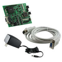
DEMO BOARD FOR PCA9564
Manufacturer
NXP Semiconductors
Datasheet
1.OM6277598.pdf
(52 pages)
Specifications of OM6277,598
Main Purpose
Interface, I2C Controller
Embedded
Yes, MCU, 8-Bit
Utilized Ic / Part
PCA9564
Primary Attributes
I2C Bus Controller, 1 8-Bit GPIO, 1 8-Bit LED Dimmer
Secondary Attributes
8 Momentary Switches, 23 LEDs
Lead Free Status / RoHS Status
Not applicable / Not applicable
Other names
568-4001
935283226598
935283226598


Use of other 80C51 type Philips microcontrollers
Any Philips 80C51 microcontroller pin to pin compatible with the P89LV51Rx2 device can be used as to interface with
the PCA9564.
•
•
•
Use of any other non 80C51 type master devices
Any other non-80C51 type microprocessor, DSP, ASIC or emulator can be used with the PCA9564 evaluation board.
When an external device is used:
1) Remove the P89LV51RD2 microcontroller from its socket
2) Apply the 8-bit parallel bus data on connector JP16. Built-in pull up resistors can be disconnected by opening the
3) Apply PCA9564 control signals and monitor Interrupt pin (open drain output) on connector JP14
Caution: Since the PCA9564 is 5.5 V tolerant, no voltage greater than 5.5 V must be applied to the parallel bus
data and the control signals
Communication between the 2 microcontrollers
•
•
Power supply:
It can be chosen from:
-
-
If an external voltage is applied to the microcontroller, digital signals interfacing with the PCA9564 will be pulled
up to this external voltage value.
Caution: Since the PCA9564 is 5.5 V tolerant, no voltage greater than 5.5 V must be applied to the
VDDMCU+ pin.
Microcontroller with built-in I
Port P1.6 (SCL) and P1.7 (SDA) can be connected to the internal I
and JP13.
-
-
-
-
ISP mode:
ISP mode for P89C51Rx+/Rx2/66x devices can also be entered by forcing the /PSEN pin to LOW. This is
performed through the jumper JP9.
-
-
jumper VDDMCU+.
Note: RESET pushbutton (S9) cannot longer be used when VDDMCU+ is open
Communication through the I
Jumpers JP6 and JP7 allow to connect or split the I
I
I
JP13 are closed).
-
-
-
-
Since the PCA9564 is a multi-master capable device, both microcontrollers can be a master in the same bus (when
JP6 and JP7 closed). If both masters try to take control of the I
be performed between the P89LV51RD2/PCA9564 and the P89LPC932.
Communication through RxD and TxD pins:
An additional non-I
TxD pins.
P89LV51 TxD pin can be connected to the P89LPC932 RxD pin through jumper JP17
-
-
2
2
C-bus 1 contains the following devices: P89LV51RD2/ PCA9564, PCA9531, PCF85116 and PCA9554A
C-bus 2 contains the following devices: P89LPC932, P89xx51 with built-in SCL/SDA (when jumpers JP12 and
The internal 3.3 V regulated voltage: Jumper VDDMCU+ closed
An external regulated voltage:
JP12 open: P1.6 not connected to SCL2
JP12 closed: P1.6 connected to SCL2
JP13 open: P1.7 not connected to SDA2
JP13 closed: P1.7 connected to SDA2
JP9 open:
JP9 closed:
JP6 open:
JP6 closed: SCL Bus 1 and SCL Bus 2 are connected together
JP7 open:
JP7 closed: SDA Bus 1 and SDA Bus 2 are connected together
JP17 open:
JP17 closed: pins are connected together
PSEN
SCL Bus 1 and SCL Bus 2 are not connected together
SDA Bus 1 and SDA Bus 2 are not connected together
PSEN
pins are not connected together
2
C communication channel between the 2 microcontrollers is available through their RxD and
floating
forced to ground
2
2
C-bus:
C interface:
Jumper VDDMCU+ open, external voltage applied to VCCMCU+
2
C-bus in one same bus or 2 different buses.
10
2
C-bus at the same time, an arbitration procedure will
2
C-bus 2 (connector JP5) through jumpers JP12
Related parts for OM6277,598
Image
Part Number
Description
Manufacturer
Datasheet
Request
R

Part Number:
Description:
Display Modules & Development Tools I2C BUS CONTROLLER EVAL BOARD
Manufacturer:
NXP Semiconductors

Part Number:
Description:
NXP Semiconductors designed the LPC2420/2460 microcontroller around a 16-bit/32-bitARM7TDMI-S CPU core with real-time debug interfaces that include both JTAG andembedded trace
Manufacturer:
NXP Semiconductors
Datasheet:

Part Number:
Description:
NXP Semiconductors designed the LPC2458 microcontroller around a 16-bit/32-bitARM7TDMI-S CPU core with real-time debug interfaces that include both JTAG andembedded trace
Manufacturer:
NXP Semiconductors
Datasheet:
Part Number:
Description:
NXP Semiconductors designed the LPC2468 microcontroller around a 16-bit/32-bitARM7TDMI-S CPU core with real-time debug interfaces that include both JTAG andembedded trace
Manufacturer:
NXP Semiconductors
Datasheet:
Part Number:
Description:
NXP Semiconductors designed the LPC2470 microcontroller, powered by theARM7TDMI-S core, to be a highly integrated microcontroller for a wide range ofapplications that require advanced communications and high quality graphic displays
Manufacturer:
NXP Semiconductors
Datasheet:
Part Number:
Description:
NXP Semiconductors designed the LPC2478 microcontroller, powered by theARM7TDMI-S core, to be a highly integrated microcontroller for a wide range ofapplications that require advanced communications and high quality graphic displays
Manufacturer:
NXP Semiconductors
Datasheet:
Part Number:
Description:
The Philips Semiconductors XA (eXtended Architecture) family of 16-bit single-chip microcontrollers is powerful enough to easily handle the requirements of high performance embedded applications, yet inexpensive enough to compete in the market for hi
Manufacturer:
NXP Semiconductors
Datasheet:
Part Number:
Description:
The XA-S3 device is a member of Philips Semiconductors? XA(eXtended Architecture) family of high performance 16-bitsingle-chip microcontrollers
Manufacturer:
NXP Semiconductors
Datasheet:

Part Number:
Description:
The NXP BlueStreak LH75401/LH75411 family consists of two low-cost 16/32-bit System-on-Chip (SoC) devices
Manufacturer:
NXP Semiconductors
Datasheet:
Part Number:
Description:
The NXP LPC3130/3131 combine an 180 MHz ARM926EJ-S CPU core, high-speed USB2
Manufacturer:
NXP Semiconductors
Datasheet:
Part Number:
Description:
The NXP LPC3141 combine a 270 MHz ARM926EJ-S CPU core, High-speed USB 2
Manufacturer:
NXP Semiconductors
Part Number:
Description:
The NXP LPC3143 combine a 270 MHz ARM926EJ-S CPU core, High-speed USB 2
Manufacturer:
NXP Semiconductors

Part Number:
Description:
The NXP LPC3152 combines an 180 MHz ARM926EJ-S CPU core, High-speed USB 2
Manufacturer:
NXP Semiconductors
Part Number:
Description:
The NXP LPC3154 combines an 180 MHz ARM926EJ-S CPU core, High-speed USB 2
Manufacturer:
NXP Semiconductors