OM6277,598 NXP Semiconductors, OM6277,598 Datasheet - Page 26
OM6277,598
Manufacturer Part Number
OM6277,598
Description
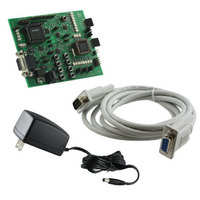
DEMO BOARD FOR PCA9564
Manufacturer
NXP Semiconductors
Datasheet
1.OM6277598.pdf
(52 pages)
Specifications of OM6277,598
Main Purpose
Interface, I2C Controller
Embedded
Yes, MCU, 8-Bit
Utilized Ic / Part
PCA9564
Primary Attributes
I2C Bus Controller, 1 8-Bit GPIO, 1 8-Bit LED Dimmer
Secondary Attributes
8 Momentary Switches, 23 LEDs
Lead Free Status / RoHS Status
Not applicable / Not applicable
Other names
568-4001
935283226598
935283226598


Message1.nrBytes = 7;
Buffer1[0]
Buffer1[1]
Buffer1[2]
Buffer1[3]
Buffer1[4]
Buffer1[5]
Buffer1[6]
I2C_Write(&Message1);
Frequency_0 = Buffer1[1];
DutyCycle_0 = Buffer1[2];
Frequency_1 = Buffer1[3];
DutyCycle_1 = Buffer1[4];
while (Buffer3[0]!=0x7F)
{
GPIO_Interrupt_Handler();
InsertDelay(100);
Message1.nrBytes = 2;
if (Buffer3[0]!=0xFF)
{
switch (Buffer3[0])
{
case 0x7F : break;
case 0xFB : if (BR_Select == 0) // Action on pushbutton selecting Blinking Rate to be programmed
case 0xBF : LED3 = 1;
= 0x11;
= 0x80;
= 0x80;
= 0x80;
= 0x80;
= 0xAA;
= 0xFF;
{
}
else
{
}
break;
Message2.address = PCA9531_WR; // Action on pushbutton - outputs to be either off or blinking
Message2.buf
Message2.nrBytes = 1;
Buffer2[0]
Message3.address = PCA9531_RD;
Message3.buf
Message3.nrBytes = 2;
I2C_WriteRepRead(&Message2,&Message3);
if (BR_Select == 0)
{
}
if (BR_Select == 1)
{
}
break;
BR_Select = 1;
LED2 = 0;
Buffer3[0] = 0xFF;
break;
BR_Select = 0
LED2 = 1;
Buffer3[0] = 0xFF;
if (Buffer3[0] == 0x00)
{
}
if (Buffer3[0] == 0xAA)
{
}
if (Buffer3[1] == 0x00)
{
}
if (Buffer3[1] == 0xFF)
{
}
Buffer1[0]= 0x05;
Buffer1[1] = 0xAA;
I2C_Write(&Message1);
Buffer1[0]= 0x05;
Buffer1[1] = 0x00;
I2C_Write(&Message1);
Buffer1[0]= 0x06;
Buffer1[1] = 0xFF;
I2C_Write(&Message1);
Buffer1[0]= 0x06;
Buffer1[1] = 0x00;
I2C_Write(&Message1);
// Reset the PCA9531 to its default programmed values
// subaddress = 0x01
// default prescaler pwm0
// default duty cycle for pwm0
// default prescaler pwm1
// default duty cycle for pwm1
// LD1 to LD4 blinking at BR0
// LD5 to LD8 blinking at BR1
// Program PCA9531 with default values
// Main loop as long as S8 (exit Program) has not been pushed
// Check if an action on pushbutton happened
// Small delay for LED dimmer visual purpose (wait between device programming)
// 2 bytes will be sent to the PCA9531 (pointer + register to be modified)
// Execute the command associated with the action on pushbutton
= Buffer2;
= 0x15;
= Buffer3;
// Exit Program 1- Push on S8 detected
// Blinking Rate 1 selected to be modified - LD[4:8]
// LD11 on
// Blinking Rate 0 selected to be modified - LD[1:4]
// LD11 off
// LD12 = off --> Default programming overwritten
// subaddress = 15
// read 2 bytes
26
// read output states of the PCA9531
// subaddress = 0x05
// LD[1:4] blinking at BR0
// send new data to PCA9531 (2 bytes)
// subaddress = 0x05
// LD[1:4] off
// send new data to PCA9531 (2 bytes)
// subaddress = 0x05
// LD[4:8] blinking at BR1
// send new data to PCA9531 (2 bytes)
// subaddress = 0x05
// LD[4:8] off
// send new data to PCA9531 (2 bytes)
(7 bytes)
Related parts for OM6277,598
Image
Part Number
Description
Manufacturer
Datasheet
Request
R

Part Number:
Description:
Display Modules & Development Tools I2C BUS CONTROLLER EVAL BOARD
Manufacturer:
NXP Semiconductors

Part Number:
Description:
NXP Semiconductors designed the LPC2420/2460 microcontroller around a 16-bit/32-bitARM7TDMI-S CPU core with real-time debug interfaces that include both JTAG andembedded trace
Manufacturer:
NXP Semiconductors
Datasheet:

Part Number:
Description:
NXP Semiconductors designed the LPC2458 microcontroller around a 16-bit/32-bitARM7TDMI-S CPU core with real-time debug interfaces that include both JTAG andembedded trace
Manufacturer:
NXP Semiconductors
Datasheet:
Part Number:
Description:
NXP Semiconductors designed the LPC2468 microcontroller around a 16-bit/32-bitARM7TDMI-S CPU core with real-time debug interfaces that include both JTAG andembedded trace
Manufacturer:
NXP Semiconductors
Datasheet:
Part Number:
Description:
NXP Semiconductors designed the LPC2470 microcontroller, powered by theARM7TDMI-S core, to be a highly integrated microcontroller for a wide range ofapplications that require advanced communications and high quality graphic displays
Manufacturer:
NXP Semiconductors
Datasheet:
Part Number:
Description:
NXP Semiconductors designed the LPC2478 microcontroller, powered by theARM7TDMI-S core, to be a highly integrated microcontroller for a wide range ofapplications that require advanced communications and high quality graphic displays
Manufacturer:
NXP Semiconductors
Datasheet:
Part Number:
Description:
The Philips Semiconductors XA (eXtended Architecture) family of 16-bit single-chip microcontrollers is powerful enough to easily handle the requirements of high performance embedded applications, yet inexpensive enough to compete in the market for hi
Manufacturer:
NXP Semiconductors
Datasheet:
Part Number:
Description:
The XA-S3 device is a member of Philips Semiconductors? XA(eXtended Architecture) family of high performance 16-bitsingle-chip microcontrollers
Manufacturer:
NXP Semiconductors
Datasheet:

Part Number:
Description:
The NXP BlueStreak LH75401/LH75411 family consists of two low-cost 16/32-bit System-on-Chip (SoC) devices
Manufacturer:
NXP Semiconductors
Datasheet:
Part Number:
Description:
The NXP LPC3130/3131 combine an 180 MHz ARM926EJ-S CPU core, high-speed USB2
Manufacturer:
NXP Semiconductors
Datasheet:
Part Number:
Description:
The NXP LPC3141 combine a 270 MHz ARM926EJ-S CPU core, High-speed USB 2
Manufacturer:
NXP Semiconductors
Part Number:
Description:
The NXP LPC3143 combine a 270 MHz ARM926EJ-S CPU core, High-speed USB 2
Manufacturer:
NXP Semiconductors

Part Number:
Description:
The NXP LPC3152 combines an 180 MHz ARM926EJ-S CPU core, High-speed USB 2
Manufacturer:
NXP Semiconductors
Part Number:
Description:
The NXP LPC3154 combines an 180 MHz ARM926EJ-S CPU core, High-speed USB 2
Manufacturer:
NXP Semiconductors