OM6277,598 NXP Semiconductors, OM6277,598 Datasheet - Page 8
OM6277,598
Manufacturer Part Number
OM6277,598
Description
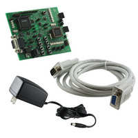
DEMO BOARD FOR PCA9564
Manufacturer
NXP Semiconductors
Datasheet
1.OM6277598.pdf
(52 pages)
Specifications of OM6277,598
Main Purpose
Interface, I2C Controller
Embedded
Yes, MCU, 8-Bit
Utilized Ic / Part
PCA9564
Primary Attributes
I2C Bus Controller, 1 8-Bit GPIO, 1 8-Bit LED Dimmer
Secondary Attributes
8 Momentary Switches, 23 LEDs
Lead Free Status / RoHS Status
Not applicable / Not applicable
Other names
568-4001
935283226598
935283226598


Pushbuttons – User interface and Reset
•
•
In-System Programming Mode
P89LV51RD2 and P89LPC932 devices have a built-in ISP (In-System Programming) algorithm allowing them to be
programmed without the need to remove them from the application. Also, a previously programmed device can be
erased and reprogrammed without removal from the circuit board. In order to perform ISP operations, the
microcontroller is powered up in a special “ISP mode”. ISP mode allows the microcontroller to communicate with an
external host device through the serial port, such as a PC or terminal. The microcontroller receives commands and data
from the host, erases and reprograms code memory, etc. Once the ISP operations have been completed, the device is
reconfigured so that it will operate normally the next time it is either reset or power cycled.
Pushbuttons can be used in 2 different modes with the embedded programs:
-
Pushbuttons S1 to S8:
They are connected to the 8 inputs of the PCA9554A, I
an interface between the user and the microcontroller(s) to perform actions such as program selection, user
definable events …
The microcontroller(s) can either:
-
-
-
-
Notes:
Pushbutton S9:
Pushbutton S9 (RESET), when pressed, performs a reset to both P89LV51RD2 and PCA9531 devices to their
power up default states. It is also used to enter and exit the P89LV51RD2 ISP mode (for more detail, refer to the
paragraph “In-System Programming Mode”.
-
Polling or interrupt monitoring of the PCA9554A by the P89LPC932 microcontroller requires having jumpers
Poll the PCA9554A in order to read the input register and the state of the switches.
Reading of the input port is performed by:
1. Sending the PCA9554A I
2. A Re-Start Command followed by the PCA9554A I
3. Reading the input port register byte from the PCA9554A.
Monitor the PCA9554A Interrupt output pin in order to detect change(s) in the switches.
When one or more input change states:
1. The PCA9554A Interrupt output will go LOW, thus indicating to the microcontroller that a switch has
2. The microcontroller can then perform the same reading sequence as explained above in order to determine
Single shot mode: a single push then release is detected. The action associated with the pushbutton is executed
once.
1. An Interrupt is detected by the master (P89LV51RD2) when a pushbutton is pressed.
2. P89LV51RD2 initiates a read of the PCA9554A input register (first snapshot).
3. P89LV51RD2 initiates a second reading of the PCA9554A input register (second snapshot) about 750 ms
If the second reading indicates a pushbutton idle condition, then the action read the first time is performed
once.
Permanent push mode: the user keeps the pushbutton pushed and the master executes the associated
command until the pushbutton is released again.
1. An Interrupt is detected by the master (P89LV51RD2) when a pushbutton is pressed
2. P89LV51RD2 initiates a read of the PCA9554A input register (first snapshot)
3. P89LV51RD2 initiates a second read of the PCA9554A input register (second snapshot) about 750 ms
If the second read is the same as the first one, then the master will continue to poll the PCA9554A input
register and execute the associated command until the user releases the pushbutton.
JP11.
Connection of the PCA9554A Interrupt pin to the P89LV51RD2 or to the P89LPC932 is done through jumper
JP6 and JP7 closed. I
I
a) JP11 between 1 and 2 connects the PCA9554A Interrupt pin to the P89LPC932 device
b) JP11 between 2 and 3 connects the PCA9554A Interrupt pin to the P89LV51 device
2
C-bus 1.
been pressed and the Interrupt service routine needs to be initiated.
which input changes state. Reading the PCA9554A will automatically clear its interrupt.
later.
after
2
C-bus 1 and I
2
C address with a Write command followed by 0x00 (Input register pointer).
2
C-bus 2 need to be connected together since the PCA9554A is located on
8
2
C General Purpose Input Output device and can be used as
2
C address with a Read command.
Related parts for OM6277,598
Image
Part Number
Description
Manufacturer
Datasheet
Request
R

Part Number:
Description:
Display Modules & Development Tools I2C BUS CONTROLLER EVAL BOARD
Manufacturer:
NXP Semiconductors

Part Number:
Description:
NXP Semiconductors designed the LPC2420/2460 microcontroller around a 16-bit/32-bitARM7TDMI-S CPU core with real-time debug interfaces that include both JTAG andembedded trace
Manufacturer:
NXP Semiconductors
Datasheet:

Part Number:
Description:
NXP Semiconductors designed the LPC2458 microcontroller around a 16-bit/32-bitARM7TDMI-S CPU core with real-time debug interfaces that include both JTAG andembedded trace
Manufacturer:
NXP Semiconductors
Datasheet:
Part Number:
Description:
NXP Semiconductors designed the LPC2468 microcontroller around a 16-bit/32-bitARM7TDMI-S CPU core with real-time debug interfaces that include both JTAG andembedded trace
Manufacturer:
NXP Semiconductors
Datasheet:
Part Number:
Description:
NXP Semiconductors designed the LPC2470 microcontroller, powered by theARM7TDMI-S core, to be a highly integrated microcontroller for a wide range ofapplications that require advanced communications and high quality graphic displays
Manufacturer:
NXP Semiconductors
Datasheet:
Part Number:
Description:
NXP Semiconductors designed the LPC2478 microcontroller, powered by theARM7TDMI-S core, to be a highly integrated microcontroller for a wide range ofapplications that require advanced communications and high quality graphic displays
Manufacturer:
NXP Semiconductors
Datasheet:
Part Number:
Description:
The Philips Semiconductors XA (eXtended Architecture) family of 16-bit single-chip microcontrollers is powerful enough to easily handle the requirements of high performance embedded applications, yet inexpensive enough to compete in the market for hi
Manufacturer:
NXP Semiconductors
Datasheet:
Part Number:
Description:
The XA-S3 device is a member of Philips Semiconductors? XA(eXtended Architecture) family of high performance 16-bitsingle-chip microcontrollers
Manufacturer:
NXP Semiconductors
Datasheet:

Part Number:
Description:
The NXP BlueStreak LH75401/LH75411 family consists of two low-cost 16/32-bit System-on-Chip (SoC) devices
Manufacturer:
NXP Semiconductors
Datasheet:
Part Number:
Description:
The NXP LPC3130/3131 combine an 180 MHz ARM926EJ-S CPU core, high-speed USB2
Manufacturer:
NXP Semiconductors
Datasheet:
Part Number:
Description:
The NXP LPC3141 combine a 270 MHz ARM926EJ-S CPU core, High-speed USB 2
Manufacturer:
NXP Semiconductors
Part Number:
Description:
The NXP LPC3143 combine a 270 MHz ARM926EJ-S CPU core, High-speed USB 2
Manufacturer:
NXP Semiconductors

Part Number:
Description:
The NXP LPC3152 combines an 180 MHz ARM926EJ-S CPU core, High-speed USB 2
Manufacturer:
NXP Semiconductors
Part Number:
Description:
The NXP LPC3154 combines an 180 MHz ARM926EJ-S CPU core, High-speed USB 2
Manufacturer:
NXP Semiconductors