OM6277,598 NXP Semiconductors, OM6277,598 Datasheet - Page 9
OM6277,598
Manufacturer Part Number
OM6277,598
Description
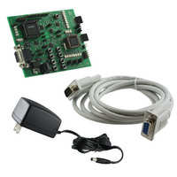
DEMO BOARD FOR PCA9564
Manufacturer
NXP Semiconductors
Datasheet
1.OM6277598.pdf
(52 pages)
Specifications of OM6277,598
Main Purpose
Interface, I2C Controller
Embedded
Yes, MCU, 8-Bit
Utilized Ic / Part
PCA9564
Primary Attributes
I2C Bus Controller, 1 8-Bit GPIO, 1 8-Bit LED Dimmer
Secondary Attributes
8 Momentary Switches, 23 LEDs
Lead Free Status / RoHS Status
Not applicable / Not applicable
Other names
568-4001
935283226598
935283226598


ISP programming for both devices can be done using Flash Magic. Flash Magic is a free, powerful, feature-rich
Windows application that allows easy programming of Philips Flash microcontrollers. Flash Magic uses Intel Hex files
as input to program the targeted device. For download information, refer to the paragraph “Download software,
programs and documentation”.
P89LV51RD2 ISP programming
a) Set jumpers JP2 and JP3 to target P89LV51RD2 device: both jumpers connected between 2 and 3
b) Connect the DB-9 cable between the PC serial port and the PCA9564 evaluation board DB-9 connector
c) Enter the P89LV51RD2 ISP mode as requested in the Flash Magic pop up window: This is done by pushing the
d) Open Flash Magic and go through the five following steps:
e) Exit the P89LV51RD2 ISP mode when programming done (“Finished” displayed at the bottom of the Flash Magic
f)
P89LPC932 ISP programming
a) Set jumpers JP2 and JP3 to target P89LPC932 device: both jumpers connected between 1 and 2
b) Connect the DB-9 cable between the PC serial port and the PCA9564 evaluation board DB-9 connector
c) Enter the P89LPC932 ISP mode: This is done by setting the following jumpers:
d) Open Flash Magic and go through the 6 following steps:
e) Exit the P89LV51RD2 ISP mode when programming done (“Finished” displayed at the bottom of the Flash Magic
f)
Other features
Write Protect PCF85116
JP1 allows data protection in the PCF85116 EEPROM:
RESET pushbutton (S9) one time.
Step 1: Set the connection status and the type of microcontroller to be programmed: COM port, Baud Rate (9600),
Step 2: Flash erasing (part or all)
Step 3: Select the Hex file to be loaded in the microcontroller
Step 4: Options to be set (Memory verification, Security bits…)
Step 5: Perform the operations described in the steps above (click on “START” button)
Programming of the blocks is displayed at the bottom of the Flash Magic window.
window): This is done by pushing the RESET pushbutton one time again (S9)
Once device programming has successfully been executed, the microcontroller can run the new program.
-
-
-
-
Step 1: Set the connection status and the type of microcontroller to be programmed: COM port, Baud Rate (9600),
Step 2: Go to: Options → Advanced Options → Hardware Config
Step 3: Flash erasing (part or all)
Step 4: Select the Hex file to be loaded in the microcontroller
Step 5: Options to be set (Memory verification, Security bits…)
Step 6: Perform the operations described in the steps above (click on “START” button).
Programming of the blocks is displayed at the bottom of the Flash Magic window.
window): This is done by setting:
-
-
-
Once device programming has successfully completed, exit from the ISP. The microcontroller is now ready to run
the new program.
-
-
JP10 (RSTISP) closed
JP15 (VDDISP) open
JP6 and JP7 (I2CConnect) open
JP12 (SCLLV) and JP13 (SDALV) open
JP10 (RSTISP) open
JP15 (VDDISP) closed
State of JP6, JP7, JP12 and JP13 are function of the program requirements
JP1 open:
JP1 closed: writing to the EEPROM is allowed – memory is not protected
Check the box “Use DTR and RTX to enter ISP mode”
Device = 89LPC932
Device = 89LV51RD2
data in the EEPROM is write protected
9
Related parts for OM6277,598
Image
Part Number
Description
Manufacturer
Datasheet
Request
R

Part Number:
Description:
Display Modules & Development Tools I2C BUS CONTROLLER EVAL BOARD
Manufacturer:
NXP Semiconductors

Part Number:
Description:
NXP Semiconductors designed the LPC2420/2460 microcontroller around a 16-bit/32-bitARM7TDMI-S CPU core with real-time debug interfaces that include both JTAG andembedded trace
Manufacturer:
NXP Semiconductors
Datasheet:

Part Number:
Description:
NXP Semiconductors designed the LPC2458 microcontroller around a 16-bit/32-bitARM7TDMI-S CPU core with real-time debug interfaces that include both JTAG andembedded trace
Manufacturer:
NXP Semiconductors
Datasheet:
Part Number:
Description:
NXP Semiconductors designed the LPC2468 microcontroller around a 16-bit/32-bitARM7TDMI-S CPU core with real-time debug interfaces that include both JTAG andembedded trace
Manufacturer:
NXP Semiconductors
Datasheet:
Part Number:
Description:
NXP Semiconductors designed the LPC2470 microcontroller, powered by theARM7TDMI-S core, to be a highly integrated microcontroller for a wide range ofapplications that require advanced communications and high quality graphic displays
Manufacturer:
NXP Semiconductors
Datasheet:
Part Number:
Description:
NXP Semiconductors designed the LPC2478 microcontroller, powered by theARM7TDMI-S core, to be a highly integrated microcontroller for a wide range ofapplications that require advanced communications and high quality graphic displays
Manufacturer:
NXP Semiconductors
Datasheet:
Part Number:
Description:
The Philips Semiconductors XA (eXtended Architecture) family of 16-bit single-chip microcontrollers is powerful enough to easily handle the requirements of high performance embedded applications, yet inexpensive enough to compete in the market for hi
Manufacturer:
NXP Semiconductors
Datasheet:
Part Number:
Description:
The XA-S3 device is a member of Philips Semiconductors? XA(eXtended Architecture) family of high performance 16-bitsingle-chip microcontrollers
Manufacturer:
NXP Semiconductors
Datasheet:

Part Number:
Description:
The NXP BlueStreak LH75401/LH75411 family consists of two low-cost 16/32-bit System-on-Chip (SoC) devices
Manufacturer:
NXP Semiconductors
Datasheet:
Part Number:
Description:
The NXP LPC3130/3131 combine an 180 MHz ARM926EJ-S CPU core, high-speed USB2
Manufacturer:
NXP Semiconductors
Datasheet:
Part Number:
Description:
The NXP LPC3141 combine a 270 MHz ARM926EJ-S CPU core, High-speed USB 2
Manufacturer:
NXP Semiconductors
Part Number:
Description:
The NXP LPC3143 combine a 270 MHz ARM926EJ-S CPU core, High-speed USB 2
Manufacturer:
NXP Semiconductors

Part Number:
Description:
The NXP LPC3152 combines an 180 MHz ARM926EJ-S CPU core, High-speed USB 2
Manufacturer:
NXP Semiconductors
Part Number:
Description:
The NXP LPC3154 combines an 180 MHz ARM926EJ-S CPU core, High-speed USB 2
Manufacturer:
NXP Semiconductors