STEVAL-ISQ002V1 STMicroelectronics, STEVAL-ISQ002V1 Datasheet - Page 54
STEVAL-ISQ002V1
Manufacturer Part Number
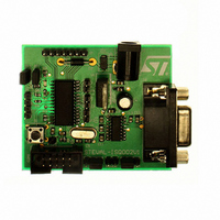
STEVAL-ISQ002V1
Description
BOARD EVAL BASED ON ST72264G1
Manufacturer
STMicroelectronics
Specifications of STEVAL-ISQ002V1
Main Purpose
Interface, PMBus
Embedded
Yes, MCU, 8-Bit
Utilized Ic / Part
ST72F264
Primary Attributes
The PMBus™ Interface Using the ST7 I2C Peripheral
Secondary Attributes
Firmware in C Language
Product
Power Management Modules
Lead Free Status / RoHS Status
Lead free / RoHS Compliant
Other names
497-6423
Available stocks
Company
Part Number
Manufacturer
Quantity
Price
Company:

Part Number:
STEVAL-ISQ002V1
Manufacturer:
STMicroelectronics
Quantity:
1


ST72260Gx, ST72262Gx, ST72264Gx
MAIN CLOCK CONTROLLER WITH REAL TIME CLOCK (Cont’d)
11.2.2 Low Power Modes
11.2.3 Interrupts
The MCC/RTC interrupt event generates an inter-
rupt if the OIE bit of the MCCSR register is set and
the interrupt mask in the CC register is not active
(RIM instruction).
Note:
The MCC/RTC interrupt wakes up the MCU from
ACTIVE-HALT mode, not from HALT mode.
11.2.4 Register Description
MCC CONTROL/STATUS REGISTER (MCCSR)
Read/Write
Reset Value: 0000 0000 (00h
Bit 7:4 = reserved
Table 13. Main Clock Controller Register Map and Reset Values
54/172
WAIT
ACTIVE-
HALT
HALT
Time base overflow
event
Address
Mode
Interrupt Event
7
0
(Hex.)
0025h
0026h
0
No effect on MCC/RTC peripheral.
MCC/RTC interrupt cause the device to exit
from WAIT mode.
No effect on MCC/RTC counter (OIE bit is
set), the registers are frozen.
MCC/RTC interrupt cause the device to exit
from ACTIVE-HALT mode.
MCC/RTC counter and registers are frozen.
MCC/RTC operation resumes when the
MCU is woken up by an interrupt with “exit
from HALT” capability.
SICSR
Reset Value
MCCSR
Reset Value
Register
0
Label
Event
Flag
0
OIF
Description
TB1
Control
Enable
7
0
OIE
0
Bit
)
TB0
from
Wait
Exit
Yes
AVDIE
OIE
6
0
0
No
from
Exit
Halt
OIF
0
1)
AVDF
5
0
0
Bit 3:2 = TB[1:0] Time base control
These bits select the programmable divider time
base. They are set and cleared by software.
A modification of the time base is taken into ac-
count at the end of the current period (previously
set) to avoid an unwanted time shift. This allows to
use this time base as a real time clock.
Bit 1 = OIE Oscillator interrupt enable
This bit set and cleared by software.
0: Oscillator interrupt disabled
1: Oscillator interrupt enabled
This interrupt can be used to exit from ACTIVE-
HALT mode.
When this bit is set, calling the ST7 software HALT
instruction enters the ACTIVE-HALT power saving
mode
Bit 0 = OIF Oscillator interrupt flag
This bit is set by hardware and cleared by software
reading the CSR register. It indicates when set
that the main oscillator has reached the selected
elapsed time (TB1:0).
0: Timeout not reached
1: Timeout reached
CAUTION: The BRES and BSET instructions
must not be used on the MCCSR register to avoid
unintentionally clearing the OIF bit.
Prescaler
Counter
LVDRF
200000
16000
32000
80000
4
x
0
.
f
OSC2
TB1
3
0
0
20ms
50ms
4ms
8ms
=4MHz f
Time Base
TB0
2
0
0
OSC2
10ms
25ms
2ms
4ms
=8MHz
OIE
1
0
0
TB1
0
0
1
1
WDGRF
OIF
0
x
0
TB0
0
1
0
1
Related parts for STEVAL-ISQ002V1
Image
Part Number
Description
Manufacturer
Datasheet
Request
R

Part Number:
Description:
BOARD RGB CTR ST7,STP08C596MTR
Manufacturer:
STMicroelectronics
Datasheet:

Part Number:
Description:
Power Management IC Development Tools Full Speed USB to RS232 Bridge Demo
Manufacturer:
STMicroelectronics
Datasheet:
Part Number:
Description:
Power Management IC Development Tools 2.5W solar eval BRD USB SPV1040 LD39050
Manufacturer:
STMicroelectronics
Datasheet:

Part Number:
Description:
BOARD EVAL FOR MEMS SENSORS
Manufacturer:
STMicroelectronics
Datasheet:

Part Number:
Description:
KIT DEV STARTER ST10F276Z5
Manufacturer:
STMicroelectronics
Datasheet:

Part Number:
Description:
BOARD EVAL HDMI $ VIDEO SWITCH
Manufacturer:
STMicroelectronics
Datasheet:

Part Number:
Description:
BOARD DEMO ACCELEROMETER DIL24
Manufacturer:
STMicroelectronics
Datasheet:

Part Number:
Description:
BOARD STLM75/STDS75/ST72F651
Manufacturer:
STMicroelectronics
Datasheet:

Part Number:
Description:
EVAL BOARD 3AXIS MEMS ACCELLRMTR
Manufacturer:
STMicroelectronics
Datasheet:

Part Number:
Description:
BOARD EVAL 8BIT MICRO + TDE1708
Manufacturer:
STMicroelectronics
Datasheet:
Part Number:
Description:
STMicroelectronics [RIPPLE-CARRY BINARY COUNTER/DIVIDERS]
Manufacturer:
STMicroelectronics
Datasheet:
Part Number:
Description:
STMicroelectronics [LIQUID-CRYSTAL DISPLAY DRIVERS]
Manufacturer:
STMicroelectronics
Datasheet:
Part Number:
Description:
BOARD EVAL FOR MEMS SENSORS
Manufacturer:
STMicroelectronics
Datasheet: