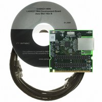
EVB9221-MINI SMSC, EVB9221-MINI Datasheet - Page 50

EVB9221-MINI
Manufacturer Part Number
EVB9221-MINI
Description
EVALUATION BOARD LAN9221-ABZJ
Manufacturer
SMSC
Datasheet
1.LAN9221-ABZJ.pdf
(152 pages)
Specifications of EVB9221-MINI
Main Purpose
Interface, Ethernet Controller (PHY and MAC)
Embedded
No
Utilized Ic / Part
LAN9221
Primary Attributes
1 Port, 100BASE-TX/10BASE-T
Secondary Attributes
16-Bit, HP Auto-MDIX, Full and Half Duplex Support, 32-Bit CRC
Processor To Be Evaluated
LAN9221
Lead Free Status / RoHS Status
Lead free / RoHS Compliant
Other names
638-1074
- Current page: 50 of 152
- Download datasheet (2Mb)
High-Performance 16-bit Non-PCI 10/100 Ethernet Controller with Variable Voltage I/O
Datasheet
‘A’ and TX command ‘B’). The TX command instructs the LAN9221/LAN9221i on the handling of the
associated buffer. Packet boundaries are delineated using control bits within the TX command.
The host provides a 16-bit Packet Tag field in the TX command. The Packet Tag value is appended
to the corresponding TX status DWORD. All Packet Tag fields must have the same value for all buffers
in a given packet. If tags differ between buffers in the same packet the TXE error will be asserted. Any
value may be chosen for a Packet Tag as long as all tags in the same Packet are identical. Packet
Tags also provide a method of synchronization between transmitted packets and their associated
status. Software can use unique Packet Tags to assist with validating matching status completions.
Note 3.20 The use of packet tags is not required by the hardware. This is a software LAN driver only
application example for use of this field.
A Packet Length field in the TX command specifies the number of bytes in the associated packet. All
Packet Length fields must have the same value for all buffers in a given packet. Hardware compares
the Packet Length field and the actual amount of data received by the Ethernet controller. If the actual
packet length count does not match the Packet Length field as defined in the TX command, the
Transmitter Error (TXE) flag is asserted.
The LAN9221/LAN9221i can be programmed to start payload transmission of a buffer on a byte
boundary by setting the “Data Start Offset” field in the TX command. The “Data Start Offset” field points
to the actual start of the payload data within the first 8 DWORDs of the buffer. Data before the “Data
Start Offset” pointer will be ignored. When a packet is split into multiple buffers, each successive buffer
may begin on any arbitrary byte.
The LAN9221/LAN9221i can be programmed to strip padding from the end of a transmit packet in the
event that the end of the packet does not align with the host burst boundary. This feature is necessary
when the LAN9221/LAN9221i is operating in a system that always performs multi-word bursts. In such
cases the LAN9221/LAN9221i must guarantee that it can accept data in multiples of the Burst length
regardless of the actual packet length. When configured to do so, the LAN9221/LAN9221i will accept
extra data at the end of the packet and will remove the extra padding before transmitting the packet.
The LAN9221/LAN9221i automatically removes data up to the boundary specified in the Buffer End
Alignment field specified in each TX command.
The host can instruct the LAN9221/LAN9221i to issue an interrupt when the buffer has been fully
loaded into the TX FIFO contained in the LAN9221/LAN9221i and transmitted. This feature is enabled
through the TX command ‘Interrupt on Completion’ field.
Upon completion of transmission, irrespective of success or failure, the status of the transmission is
written to the TX status FIFO. TX status is available to the host and may be read using PIO operations.
An interrupt can be optionally enabled by the host to indicate the availability of a programmable
number TX status DWORDS.
Before writing the TX command and payload data to the TX FIFO, the host must check the available
TX FIFO space by performing a PIO read of the TX_FIFO_INF register. The host must ensure that it
does not overfill the TX FIFO or the TX Error (TXE) flag will be asserted.
The host proceeds to write the TX command by first writing TX command ‘A’, then TX command ‘B’.
After writing the command, the host can then move the payload data into the TX FIFO. TX status
DWORD’s are stored in the TX status FIFO to be read by the host at a later time upon completion of
the data transmission onto the wire.
50
Revision 2.7 (03-15-10)
SMSC LAN9221/LAN9221i
DATASHEET
Related parts for EVB9221-MINI
Image
Part Number
Description
Manufacturer
Datasheet
Request
R

Part Number:
Description:
FAST ETHERNET PHYSICAL LAYER DEVICE
Manufacturer:
SMSC Corporation
Datasheet:

Part Number:
Description:
357-036-542-201 CARDEDGE 36POS DL .156 BLK LOPRO
Manufacturer:
SMSC Corporation
Datasheet:

Part Number:
Description:
357-036-542-201 CARDEDGE 36POS DL .156 BLK LOPRO
Manufacturer:
SMSC Corporation
Datasheet:

Part Number:
Description:
357-036-542-201 CARDEDGE 36POS DL .156 BLK LOPRO
Manufacturer:
SMSC Corporation
Datasheet:

Part Number:
Description:
4-PORT USB2.0 HUB CONTROLLER
Manufacturer:
SMSC Corporation
Datasheet:

Part Number:
Description:
Manufacturer:
SMSC Corporation
Datasheet:

Part Number:
Description:
Manufacturer:
SMSC Corporation
Datasheet:

Part Number:
Description:
FDC37C672ENHANCED SUPER I/O CONTROLLER WITH FAST IR
Manufacturer:
SMSC Corporation
Datasheet:

Part Number:
Description:
COM90C66LJPARCNET Controller/Transceiver with AT Interface and On-Chip RAM
Manufacturer:
SMSC Corporation
Datasheet:

Part Number:
Description:
Manufacturer:
SMSC Corporation
Datasheet:

Part Number:
Description:
Manufacturer:
SMSC Corporation
Datasheet:

Part Number:
Description:
Manufacturer:
SMSC Corporation
Datasheet:

Part Number:
Description:
Manufacturer:
SMSC Corporation
Datasheet:


