DEMO9S08LC60 Freescale Semiconductor, DEMO9S08LC60 Datasheet - Page 141
DEMO9S08LC60
Manufacturer Part Number
DEMO9S08LC60
Description
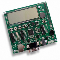
BOARD DEMO FOR 9S08LC60
Manufacturer
Freescale Semiconductor
Type
MCUr
Datasheets
1.DEMO9S08LC60.pdf
(360 pages)
2.DEMO9S08LC60.pdf
(32 pages)
3.DEMO9S08LC60.pdf
(2 pages)
Specifications of DEMO9S08LC60
Contents
Evaluation Board
Processor To Be Evaluated
MC9S08LC60
Interface Type
RS-232, USB
Silicon Manufacturer
Freescale
Core Architecture
HCS08
Core Sub-architecture
HCS08
Silicon Core Number
MC9S08
Silicon Family Name
S08LC
Rohs Compliant
Yes
For Use With/related Products
MC9S08LC60
Lead Free Status / RoHS Status
Lead free / RoHS Compliant


The value of LCDCLK is important because it is used to generate the LCD module waveform base clock
frequency.
calculation.
the LCLK[2:0] bit field.
The LCD module waveform base clock is the basis for the calculation of the LCD module frame frequency.
The LCD module frame frequency is a function of LCD module duty cycle as shown in
Table 9-15
configurations of LCLK[2:0] and DUTY[1:0]. The using LCD module frame frequency calculations a
based on LCD module clock input value approximately 32 kHz.
The LCD module frame frequency is defined as the number of times the LCD segments are energized per
second. The LCD module frame frequency must be selected to prevent the LCD display from flickering
(LCD module frame frequency is too low) or ghosting (LCD module frame frequency is too high). To
avoid these issues a LCD module frame frequency in the range of 30 to 100 Hz is required. LCD module
frame frequency less that 30 Hz or greater that 100 Hz are out of specification and invalid. Selecting lower
values for the LCD base and frame frequency results in lower current consumption for the LCD module.
9.4.1.4
This section shows the timing examples of the LCD output waveforms for the available modes of
operation. As shown in
Freescale Semiconductor
1
2
LCD clock input ~ 32.768 kHz
Shaded table entries are out of specification and are invalid.
LCLK[2:0]
LCD module frame frequency = (LCD module waveform base clock) × (duty cycle)
0
1
2
3
4
5
6
7
Equation 9-1
shows LCD module frame frequency calculations considering several possible LCD module
Equation 9-1
LCD Waveform Examples
LCD Clock Input Divider
(16 × 2
Table 9-15. LCD Module Frame Frequency Calculations
Table
provides an expression for the LCD module waveform base clock frequency
illustrates that the LCD module waveform base clock frequency also depends on
1024
2048
256
128
512
MC9S08LC60 Series Data Sheet: Technical Data, Rev. 4
LCLK[2:0]
16
32
64
9-16, all examples use 1/3 bias mode.
)
Frequency
LCD Base
2049.3
1024.7
512.3
256.2
128.1
64.0
32.0
16.0
(Hz)
512.32
256.16
128.08
64.04
32.02
16.01
1024
8.00
1/2/
Chapter 9 Liquid Crystal Display Driver (S08LCDV1)
LCD Frame Frequency (Hz)
Duty Cycle
341.55
170.77
85.38
42.69
21.34
10.67
5.33
683
1/3
1
,
2
Equation
512.32
256.16
128.08
64.04
32.02
16.01
8.00
4.00
1/4
Eqn. 9-6
9-6.
141
Related parts for DEMO9S08LC60
Image
Part Number
Description
Manufacturer
Datasheet
Request
R

Part Number:
Description:
Manufacturer:
Freescale Semiconductor, Inc
Datasheet:
Part Number:
Description:
Manufacturer:
Freescale Semiconductor, Inc
Datasheet:
Part Number:
Description:
Manufacturer:
Freescale Semiconductor, Inc
Datasheet:
Part Number:
Description:
Manufacturer:
Freescale Semiconductor, Inc
Datasheet:
Part Number:
Description:
Manufacturer:
Freescale Semiconductor, Inc
Datasheet:
Part Number:
Description:
Manufacturer:
Freescale Semiconductor, Inc
Datasheet:
Part Number:
Description:
Manufacturer:
Freescale Semiconductor, Inc
Datasheet:
Part Number:
Description:
Manufacturer:
Freescale Semiconductor, Inc
Datasheet:
Part Number:
Description:
Manufacturer:
Freescale Semiconductor, Inc
Datasheet:
Part Number:
Description:
Manufacturer:
Freescale Semiconductor, Inc
Datasheet:
Part Number:
Description:
Manufacturer:
Freescale Semiconductor, Inc
Datasheet:
Part Number:
Description:
Manufacturer:
Freescale Semiconductor, Inc
Datasheet:
Part Number:
Description:
Manufacturer:
Freescale Semiconductor, Inc
Datasheet:
Part Number:
Description:
Manufacturer:
Freescale Semiconductor, Inc
Datasheet:
Part Number:
Description:
Manufacturer:
Freescale Semiconductor, Inc
Datasheet: