DEMO9S08LC60 Freescale Semiconductor, DEMO9S08LC60 Datasheet - Page 51
DEMO9S08LC60
Manufacturer Part Number
DEMO9S08LC60
Description
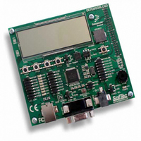
BOARD DEMO FOR 9S08LC60
Manufacturer
Freescale Semiconductor
Type
MCUr
Datasheets
1.DEMO9S08LC60.pdf
(360 pages)
2.DEMO9S08LC60.pdf
(32 pages)
3.DEMO9S08LC60.pdf
(2 pages)
Specifications of DEMO9S08LC60
Contents
Evaluation Board
Processor To Be Evaluated
MC9S08LC60
Interface Type
RS-232, USB
Silicon Manufacturer
Freescale
Core Architecture
HCS08
Core Sub-architecture
HCS08
Silicon Core Number
MC9S08
Silicon Family Name
S08LC
Rohs Compliant
Yes
For Use With/related Products
MC9S08LC60
Lead Free Status / RoHS Status
Lead free / RoHS Compliant


4.4.4
The burst program command is used to program sequential bytes of data in less time than would be
required using the standard program command. For the MC9S08LC60 Series, it is possible to burst across
FLASH array boundaries as long as the addresses are consecutive. This is possible because the high
voltage to the FLASH array does not need to be disabled between program operations. Ordinarily, when a
program or erase command is issued, an internal charge pump associated with the FLASH memory must
be enabled to supply high voltage to the array. Upon completion of the command, the charge pump is
turned off. When a burst program command is issued, the charge pump is enabled and then remains
enabled after completion of the burst program operation if these two conditions are met:
Freescale Semiconductor
•
•
The next burst program command has been queued before the current program operation has
completed.
The next sequential address selects a byte on the same physical row as the current byte being
programmed. A row of FLASH memory consists of 64 bytes. A byte within a row is selected by
addresses A5 through A0. A new row begins when addresses A5 through A0 are all zero.
Burst Program Execution
FLASH PROGRAM AND
ERASE FLOW
MC9S08LC60 Series Data Sheet: Technical Data, Rev. 4
Figure 4-2. FLASH Program and Erase Flowchart
0
TO BUFFER ADDRESS AND DATA
WRITE COMMAND TO FCMD
AND CLEAR FCBEF
TO LAUNCH COMMAND
WRITE TO FCDIV
WRITE 1 TO FCBEF
WRITE TO FLASH
CLEAR ERROR
FACCERR ?
FPVIOL OR
FACCERR ?
FCCF ?
START
DONE
1
NO
1
(Note 1)
(Note 2)
YES
0
Note 2: Wait at least four bus cycles
Note 1: Required only once after reset.
ERROR EXIT
before checking FCBEF or FCCF.
Chapter 4 Memory
51
Related parts for DEMO9S08LC60
Image
Part Number
Description
Manufacturer
Datasheet
Request
R

Part Number:
Description:
Manufacturer:
Freescale Semiconductor, Inc
Datasheet:
Part Number:
Description:
Manufacturer:
Freescale Semiconductor, Inc
Datasheet:
Part Number:
Description:
Manufacturer:
Freescale Semiconductor, Inc
Datasheet:
Part Number:
Description:
Manufacturer:
Freescale Semiconductor, Inc
Datasheet:
Part Number:
Description:
Manufacturer:
Freescale Semiconductor, Inc
Datasheet:
Part Number:
Description:
Manufacturer:
Freescale Semiconductor, Inc
Datasheet:
Part Number:
Description:
Manufacturer:
Freescale Semiconductor, Inc
Datasheet:
Part Number:
Description:
Manufacturer:
Freescale Semiconductor, Inc
Datasheet:
Part Number:
Description:
Manufacturer:
Freescale Semiconductor, Inc
Datasheet:
Part Number:
Description:
Manufacturer:
Freescale Semiconductor, Inc
Datasheet:
Part Number:
Description:
Manufacturer:
Freescale Semiconductor, Inc
Datasheet:
Part Number:
Description:
Manufacturer:
Freescale Semiconductor, Inc
Datasheet:
Part Number:
Description:
Manufacturer:
Freescale Semiconductor, Inc
Datasheet:
Part Number:
Description:
Manufacturer:
Freescale Semiconductor, Inc
Datasheet:
Part Number:
Description:
Manufacturer:
Freescale Semiconductor, Inc
Datasheet: