DEMO9S08LC60 Freescale Semiconductor, DEMO9S08LC60 Datasheet - Page 185
DEMO9S08LC60
Manufacturer Part Number
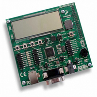
DEMO9S08LC60
Description
BOARD DEMO FOR 9S08LC60
Manufacturer
Freescale Semiconductor
Type
MCUr
Datasheets
1.DEMO9S08LC60.pdf
(360 pages)
2.DEMO9S08LC60.pdf
(32 pages)
3.DEMO9S08LC60.pdf
(2 pages)
Specifications of DEMO9S08LC60
Contents
Evaluation Board
Processor To Be Evaluated
MC9S08LC60
Interface Type
RS-232, USB
Silicon Manufacturer
Freescale
Core Architecture
HCS08
Core Sub-architecture
HCS08
Silicon Core Number
MC9S08
Silicon Family Name
S08LC
Rohs Compliant
Yes
For Use With/related Products
MC9S08LC60
Lead Free Status / RoHS Status
Lead free / RoHS Compliant


10.5.9
The reference clock and the DCO clock are monitored under different conditions (see
Provided the reference frequency is being monitored, ERCS = 1 indicates that the reference clock meets
minimum frequency requirements. When the reference and/or DCO clock(s) are being monitored, if either
one falls below a certain frequency, f
the error. LOCS will remain set until it is acknowledged or until the MCU is reset. LOCS is cleared by
reading ICGS1 then writing 1 to ICGIF (LOCRE = 0), or by a loss-of-clock induced reset (LOCRE = 1),
or by any MCU reset.
If the ICG is in FEE, a loss of reference clock causes the ICG to enter SCM, and a loss of DCO clock causes
the ICG to enter FBE mode. If the ICG is in FBE mode, a loss of reference clock will cause the ICG to
enter SCM. In each case, the CLKST and CLKS bits will be automatically changed to reflect the new state.
If the ICG is in FEE mode when a loss of clock occurs and the ERCS is still set to 1, then the CLKST bits
are set to 10 and the ICG reverts to FBE mode.
A loss of clock will also cause a loss of lock when in FEE or FEI modes. Because the method of clearing
the LOCS and LOLS bits is the same, this would only be an issue in the unlikely case that LOLRE = 1 and
LOCRE = 0. In this case, the interrupt would be overridden by the reset for the loss of lock.
Freescale Semiconductor
1
2
(CLKST = 00)
(CLKST = 01)
(CLKST = 10)
(CLKST = 11)
If ENABLE is high (waiting for external crystal start-up after exiting stop).
DCO clock will not be monitored until DCOS = 1 upon entering SCM from off or FLL bypassed external mode.
Mode
FLL Loss-of-Clock Detection
SCM
FBE
FEE
FEI
Off
0X or 11
CLKS
0X
0X
10
10
10
10
11
11
10
10
11
MC9S08LC60 Series Data Sheet: Technical Data, Rev. 4
Table 10-8. Clock Monitoring (When LOCD = 0)
REFST
X
X
X
X
X
X
0
1
0
1
0
1
LOR
and f
Forced High
Forced High
Forced Low
Forced Low
Real-Time
Forced Low
Forced Low
LOD
Real-Time
Real-Time
Real-Time
Real-Time
Real-Time
ERCS
, respectively, the LOCS status bit will be set to indicate
1
External Reference
Monitored?
Clock
Yes
Chapter 10 Internal Clock Generator (S08ICGV4)
Yes
Yes
Yes
Yes
Yes
No
No
No
No
No
No
(1)
Monitored?
DCO Clock
Table
Yes
Yes
Yes
Yes
Yes
Yes
Yes
No
No
No
No
No
(2)
(2)
(2)
2
10-8).
185
Related parts for DEMO9S08LC60
Image
Part Number
Description
Manufacturer
Datasheet
Request
R

Part Number:
Description:
Manufacturer:
Freescale Semiconductor, Inc
Datasheet:
Part Number:
Description:
Manufacturer:
Freescale Semiconductor, Inc
Datasheet:
Part Number:
Description:
Manufacturer:
Freescale Semiconductor, Inc
Datasheet:
Part Number:
Description:
Manufacturer:
Freescale Semiconductor, Inc
Datasheet:
Part Number:
Description:
Manufacturer:
Freescale Semiconductor, Inc
Datasheet:
Part Number:
Description:
Manufacturer:
Freescale Semiconductor, Inc
Datasheet:
Part Number:
Description:
Manufacturer:
Freescale Semiconductor, Inc
Datasheet:
Part Number:
Description:
Manufacturer:
Freescale Semiconductor, Inc
Datasheet:
Part Number:
Description:
Manufacturer:
Freescale Semiconductor, Inc
Datasheet:
Part Number:
Description:
Manufacturer:
Freescale Semiconductor, Inc
Datasheet:
Part Number:
Description:
Manufacturer:
Freescale Semiconductor, Inc
Datasheet:
Part Number:
Description:
Manufacturer:
Freescale Semiconductor, Inc
Datasheet:
Part Number:
Description:
Manufacturer:
Freescale Semiconductor, Inc
Datasheet:
Part Number:
Description:
Manufacturer:
Freescale Semiconductor, Inc
Datasheet:
Part Number:
Description:
Manufacturer:
Freescale Semiconductor, Inc
Datasheet: