M68EVB908GB60E Freescale Semiconductor, M68EVB908GB60E Datasheet - Page 237
M68EVB908GB60E
Manufacturer Part Number
M68EVB908GB60E
Description
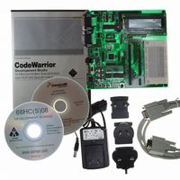
BOARD EVAL FOR MC9S08GB60
Manufacturer
Freescale Semiconductor
Type
MCUr
Datasheet
1.M68EVB908GB60E.pdf
(290 pages)
Specifications of M68EVB908GB60E
Contents
Module and Misc Hardware
Processor To Be Evaluated
MC9S08GB
Data Bus Width
8 bit
Interface Type
RS-232
Silicon Manufacturer
Freescale
Core Architecture
HCS08
Core Sub-architecture
HCS08
Silicon Core Number
MC9S08
Silicon Family Name
S08GB
Kit Contents
GB60 Evaluation Kit
Rohs Compliant
Yes
For Use With/related Products
MC9S08GB60
Lead Free Status / RoHS Status
Lead free / RoHS Compliant


15.3
All MCUs in the HCS08 Family contain a single-wire background debug interface that supports in-circuit
programming of on-chip nonvolatile memory and sophisticated non-intrusive debug capabilities. Unlike
debug interfaces on earlier 8-bit MCUs, this system does not interfere with normal application resources.
It does not use any user memory or locations in the memory map and does not share any on-chip
peripherals.
BDC commands are divided into two groups:
Typically, a relatively simple interface pod is used to translate commands from a host computer into
commands for the custom serial interface to the single-wire background debug system. Depending on the
development tool vendor, this interface pod may use a standard RS-232 serial port, a parallel printer port,
or some other type of communications such as a universal serial bus (USB) to communicate between the
host PC and the pod. The pod typically connects to the target system with ground, the BKGD pin, RESET,
and sometimes V
which is useful to regain control of a lost target system or to control startup of a target system before the
on-chip nonvolatile memory has been programmed. Sometimes V
power from the target system to avoid the need for a separate power supply. However, if the pod is powered
separately, it can be connected to a running target system without forcing a target system reset or otherwise
disturbing the running application program.
15.3.1
BKGD is the single-wire background debug interface pin. The primary function of this pin is for
bidirectional serial communication of active background mode commands and data. During reset, this pin
is used to select between starting in active background mode or starting the user’s application program.
This pin is also used to request a timed sync response pulse to allow a host development tool to determine
the correct clock frequency for background debug serial communications.
BDC serial communications use a custom serial protocol first introduced on the M68HC12 Family of
microcontrollers. This protocol assumes the host knows the communication clock rate that is determined
by the target BDC clock rate. All communication is initiated and controlled by the host that drives a
high-to-low edge to signal the beginning of each bit time. Commands and data are sent most significant bit
Freescale Semiconductor
•
•
Active background mode commands require that the target MCU is in active background mode (the
user program is not running). Active background mode commands allow the CPU registers to be
read or written, and allow the user to trace one user instruction at a time, or GO to the user program
from active background mode.
Non-intrusive commands can be executed at any time even while the user’s program is running.
Non-intrusive commands allow a user to read or write MCU memory locations or access status and
control registers within the background debug controller.
Background Debug Controller (BDC)
BKGD Pin Description
DD
. An open-drain connection to reset allows the host to force a target system reset,
Figure 15-1. BDM Tool Connector
MC9S08GB/GT Data Sheet, Rev. 2.3
NO CONNECT 3
NO CONNECT 5
BKGD
1
2
4
6
GND
RESET
V
DD
DD
can be used to allow the pod to use
Background Debug Controller (BDC)
237
Related parts for M68EVB908GB60E
Image
Part Number
Description
Manufacturer
Datasheet
Request
R

Part Number:
Description:
Manufacturer:
Freescale Semiconductor, Inc
Datasheet:
Part Number:
Description:
Manufacturer:
Freescale Semiconductor, Inc
Datasheet:
Part Number:
Description:
Manufacturer:
Freescale Semiconductor, Inc
Datasheet:
Part Number:
Description:
Manufacturer:
Freescale Semiconductor, Inc
Datasheet:
Part Number:
Description:
Manufacturer:
Freescale Semiconductor, Inc
Datasheet:
Part Number:
Description:
Manufacturer:
Freescale Semiconductor, Inc
Datasheet:
Part Number:
Description:
Manufacturer:
Freescale Semiconductor, Inc
Datasheet:
Part Number:
Description:
Manufacturer:
Freescale Semiconductor, Inc
Datasheet:
Part Number:
Description:
Manufacturer:
Freescale Semiconductor, Inc
Datasheet:
Part Number:
Description:
Manufacturer:
Freescale Semiconductor, Inc
Datasheet:
Part Number:
Description:
Manufacturer:
Freescale Semiconductor, Inc
Datasheet:
Part Number:
Description:
Manufacturer:
Freescale Semiconductor, Inc
Datasheet:
Part Number:
Description:
Manufacturer:
Freescale Semiconductor, Inc
Datasheet:
Part Number:
Description:
Manufacturer:
Freescale Semiconductor, Inc
Datasheet:
Part Number:
Description:
Manufacturer:
Freescale Semiconductor, Inc
Datasheet: