M68EVB908GB60E Freescale Semiconductor, M68EVB908GB60E Datasheet - Page 251
M68EVB908GB60E
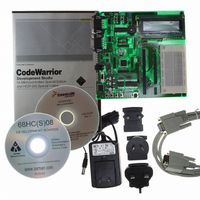
Manufacturer Part Number
M68EVB908GB60E
Description
BOARD EVAL FOR MC9S08GB60
Manufacturer
Freescale Semiconductor
Type
MCUr
Datasheet
1.M68EVB908GB60E.pdf
(290 pages)
Specifications of M68EVB908GB60E
Contents
Module and Misc Hardware
Processor To Be Evaluated
MC9S08GB
Data Bus Width
8 bit
Interface Type
RS-232
Silicon Manufacturer
Freescale
Core Architecture
HCS08
Core Sub-architecture
HCS08
Silicon Core Number
MC9S08
Silicon Family Name
S08GB
Kit Contents
GB60 Evaluation Kit
Rohs Compliant
Yes
For Use With/related Products
MC9S08GB60
Lead Free Status / RoHS Status
Lead free / RoHS Compliant


CLKSW — Select Source for BDC Communications Clock
WS — Wait or Stop Status
WSF — Wait or Stop Failure Status
DVF — Data Valid Failure Status
15.5.1.2 BDC Breakpoint Match Register (BDCBKPT)
This 16-bit register holds the address for the hardware breakpoint in the BDC. The BKPTEN and FTS
control bits in BDCSCR are used to enable and configure the breakpoint logic. Dedicated serial BDC
commands (READ_BKPT and WRITE_BKPT) are used to read and write the BDCBKPT register but is
not accessible to user programs because it is not located in the normal memory map of the MCU.
Breakpoints are normally set while the target MCU is in active background mode before running the user
application program. For additional information about setup and use of the hardware breakpoint logic in
the BDC, refer to
15.5.2
This register contains a single write-only control bit. A serial active background mode command such as
WRITE_BYTE must be used to write to SBDFR. Attempts to write this register from a user program are
ignored. Reads always return $00.
Freescale Semiconductor
CLKSW defaults to 0, which selects the alternate BDC clock source.
When the target CPU is in wait or stop mode, most BDC commands cannot function. However, the
BACKGROUND command can be used to force the target CPU out of wait or stop and into active
background mode where all BDC commands work. Whenever the host forces the target MCU into
active background mode, the host should issue a READ_STATUS command to check that
BDMACT = 1 before attempting other BDC commands.
This status bit is set if a memory access command failed due to the target CPU executing a wait or stop
instruction at or about the same time. The usual recovery strategy is to issue a BACKGROUND
command to get out of wait or stop mode into active background mode, repeat the command that failed,
then return to the user program. (Typically, the host would restore CPU registers and stack values and
re-execute the wait or stop instruction.)
This status bit is not used in the MC9S08GB/GT because it does not have any slow access memory.
1 = MCU bus clock.
0 = Alternate BDC clock source.
1 = Target CPU is in wait or stop mode, or a BACKGROUND command was used to change from
0 = Target CPU is running user application code or in active background mode (was not in wait or
1 = Memory access command failed because the CPU entered wait or stop mode.
0 = Memory access did not conflict with a wait or stop instruction.
1 = Memory access command failed because CPU was not finished with a slow memory access.
0 = Memory access did not conflict with a slow memory access.
wait or stop to active background mode.
stop mode when background became active).
System Background Debug Force Reset Register (SBDFR)
Section 15.3.4, “BDC Hardware
MC9S08GB/GT Data Sheet, Rev. 2.3
Breakpoint.”
Registers and Control Bits
251
Related parts for M68EVB908GB60E
Image
Part Number
Description
Manufacturer
Datasheet
Request
R

Part Number:
Description:
Manufacturer:
Freescale Semiconductor, Inc
Datasheet:
Part Number:
Description:
Manufacturer:
Freescale Semiconductor, Inc
Datasheet:
Part Number:
Description:
Manufacturer:
Freescale Semiconductor, Inc
Datasheet:
Part Number:
Description:
Manufacturer:
Freescale Semiconductor, Inc
Datasheet:
Part Number:
Description:
Manufacturer:
Freescale Semiconductor, Inc
Datasheet:
Part Number:
Description:
Manufacturer:
Freescale Semiconductor, Inc
Datasheet:
Part Number:
Description:
Manufacturer:
Freescale Semiconductor, Inc
Datasheet:
Part Number:
Description:
Manufacturer:
Freescale Semiconductor, Inc
Datasheet:
Part Number:
Description:
Manufacturer:
Freescale Semiconductor, Inc
Datasheet:
Part Number:
Description:
Manufacturer:
Freescale Semiconductor, Inc
Datasheet:
Part Number:
Description:
Manufacturer:
Freescale Semiconductor, Inc
Datasheet:
Part Number:
Description:
Manufacturer:
Freescale Semiconductor, Inc
Datasheet:
Part Number:
Description:
Manufacturer:
Freescale Semiconductor, Inc
Datasheet:
Part Number:
Description:
Manufacturer:
Freescale Semiconductor, Inc
Datasheet:
Part Number:
Description:
Manufacturer:
Freescale Semiconductor, Inc
Datasheet: