M68EVB908GB60E Freescale Semiconductor, M68EVB908GB60E Datasheet - Page 38
M68EVB908GB60E
Manufacturer Part Number
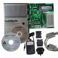
M68EVB908GB60E
Description
BOARD EVAL FOR MC9S08GB60
Manufacturer
Freescale Semiconductor
Type
MCUr
Datasheet
1.M68EVB908GB60E.pdf
(290 pages)
Specifications of M68EVB908GB60E
Contents
Module and Misc Hardware
Processor To Be Evaluated
MC9S08GB
Data Bus Width
8 bit
Interface Type
RS-232
Silicon Manufacturer
Freescale
Core Architecture
HCS08
Core Sub-architecture
HCS08
Silicon Core Number
MC9S08
Silicon Family Name
S08GB
Kit Contents
GB60 Evaluation Kit
Rohs Compliant
Yes
For Use With/related Products
MC9S08GB60
Lead Free Status / RoHS Status
Lead free / RoHS Compliant


Chapter 3 Modes of Operation
I/O Pins
Memory
ICG — In stop3 mode, the ICG enters its low-power standby state. Either the oscillator or the internal
reference may be kept running when the ICG is in standby by setting the appropriate control bit. In both
stop2 and stop1 modes, the ICG is turned off. Neither the oscillator nor the internal reference can be kept
running in stop2 or stop1, even if enabled within the ICG module.
TPM — When the MCU enters stop mode, the clock to the TPM1 and TPM2 modules stop. The modules
halt operation. If the MCU is configured to go into stop2 or stop1 mode, the TPM modules will be reset
upon wake-up from stop and must be reinitialized.
ATD — When the MCU enters stop mode, the ATD will enter a low-power standby state
operation will occur while in stop. If the MCU is configured to go into stop2 or stop1 mode, the ATD will
be reset upon wake-up from stop and must be reinitialized.
KBI — During stop3, the KBI pins that are enabled continue to function as interrupt sources that are
capable of waking the MCU from stop3. The KBI is disabled in stop1 and stop2 and must be reinitialized
after waking up from either of these modes.
SCI — When the MCU enters stop mode, the clocks to the SCI1 and SCI2 modules stop. The modules
halt operation. If the MCU is configured to go into stop2 or stop1 mode, the SCI modules will be reset
upon wake-up from stop and must be reinitialized.
SPI — When the MCU enters stop mode, the clocks to the SPI module stop. The module halts operation.
If the MCU is configured to go into stop2 or stop1 mode, the SPI module will be reset upon wake-up from
stop and must be reinitialized.
IIC — When the MCU enters stop mode, the clocks to the IIC module stops. The module halts operation.
If the MCU is configured to go into stop2 or stop1 mode, the IIC module will be reset upon wake-up from
stop and must be reinitialized.
Voltage Regulator — The voltage regulator enters a low-power standby state when the MCU enters any
of the stop modes unless the LVD is enabled in stop mode or BDM is enabled.
38
•
•
•
•
•
•
All I/O pin states remain unchanged when the MCU enters stop3 mode.
If the MCU is configured to go into stop2 mode, all I/O pins states are latched before entering stop.
If the MCU is configured to go into stop1 mode, all I/O pins are forced to their default reset state
upon entry into stop.
All RAM and register contents are preserved while the MCU is in stop3 mode.
All registers will be reset upon wake-up from stop2, but the contents of RAM are preserved and
pin states remain latched until the PPDACK bit is written. The user may save any memory-mapped
register data into RAM before entering stop2 and restore the data upon exit from stop2.
All registers will be reset upon wake-up from stop1 and the contents of RAM are not preserved.
The MCU must be initialized as upon reset. The contents of the FLASH memory are nonvolatile
and are preserved in any of the stop modes.
MC9S08GB/GT Data Sheet, Rev. 2.3
Freescale Semiconductor
.
No conversion
Related parts for M68EVB908GB60E
Image
Part Number
Description
Manufacturer
Datasheet
Request
R

Part Number:
Description:
Manufacturer:
Freescale Semiconductor, Inc
Datasheet:
Part Number:
Description:
Manufacturer:
Freescale Semiconductor, Inc
Datasheet:
Part Number:
Description:
Manufacturer:
Freescale Semiconductor, Inc
Datasheet:
Part Number:
Description:
Manufacturer:
Freescale Semiconductor, Inc
Datasheet:
Part Number:
Description:
Manufacturer:
Freescale Semiconductor, Inc
Datasheet:
Part Number:
Description:
Manufacturer:
Freescale Semiconductor, Inc
Datasheet:
Part Number:
Description:
Manufacturer:
Freescale Semiconductor, Inc
Datasheet:
Part Number:
Description:
Manufacturer:
Freescale Semiconductor, Inc
Datasheet:
Part Number:
Description:
Manufacturer:
Freescale Semiconductor, Inc
Datasheet:
Part Number:
Description:
Manufacturer:
Freescale Semiconductor, Inc
Datasheet:
Part Number:
Description:
Manufacturer:
Freescale Semiconductor, Inc
Datasheet:
Part Number:
Description:
Manufacturer:
Freescale Semiconductor, Inc
Datasheet:
Part Number:
Description:
Manufacturer:
Freescale Semiconductor, Inc
Datasheet:
Part Number:
Description:
Manufacturer:
Freescale Semiconductor, Inc
Datasheet:
Part Number:
Description:
Manufacturer:
Freescale Semiconductor, Inc
Datasheet: