Z8F083A0128ZCOG Zilog, Z8F083A0128ZCOG Datasheet - Page 96
Z8F083A0128ZCOG
Manufacturer Part Number
Z8F083A0128ZCOG
Description
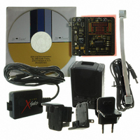
KIT DEVELOPMENT F083A
Manufacturer
Zilog
Series
Z8 Encore! XP®r
Type
MCUr
Specifications of Z8F083A0128ZCOG
Contents
Hardware, Software and Documentation
For Use With/related Products
Z8F083A
For Use With
269-4661 - KIT ACC ETHERNET SMART CABLE
Lead Free Status / RoHS Status
Lead free / RoHS Compliant
Other names
269-4672
Available stocks
Company
Part Number
Manufacturer
Quantity
Price
Company:

Part Number:
Z8F083A0128ZCOG
Manufacturer:
Zilog
Quantity:
1


PS026308-1207
Caution:
Caution:
PRES—Prescale value.
The timer input clock is divided by 2
reset each time the timer is disabled. This reset ensures proper clock division each time the
timer is restarted.
•
•
•
•
•
•
•
•
When the timer output alternate function TxOUT on a GPIO port pin is enabled, TxOUT
will change to whatever state the TPOL bit is in. The timer does not need to be enabled
for that to happen. Also, the port data direction sub register is not needed to be set to
output on TxOUT. Changing the TPOL bit when the timer is enabled and running does
not immediately change the polarity TxOUT.
PWM DUAL OUTPUT Mode
0 = Timer output is forced low (0) and timer output complement is forced high (1),
when the timer is disabled. When enabled and the PWM count matches, the timer
output is forced high (1) and forced low (0) when enabled and reloaded. When
enabled and the PWM count matches, the timer output complement is forced low (0)
and forced high (1) when enabled and reloaded.
1 = Timer output is forced high (1) and timer output complement is forced low (0)
when the timer is disabled. When enabled and the PWM count matches, the timer
output is forced low (0) and forced high (1) when enabled and reloaded.When enabled
and the PWM count matches, the timer output complement is forced high (1) and
forced low (0) when enabled and reloaded. The PWMD field in the TxCTL0 register
determiners an optional added delay on the assertion (low to high) transition of both
timer output and timer output complement for deadband generation.
CAPTURE RESTART Mode
0 = Count is captured on the rising edge of the timer input signal.
1 = Count is captured on the falling edge of the timer input signal.
COMPARATOR COUNTER Mode
When the timer is disabled, the timer output signal is set to the value of this bit. When
the timer is enabled, the timer output signal is complemented on timer reload.
000 = Divide by 1
001 = Divide by 2
010 = Divide by 4
011 = Divide by 8
100 = Divide by 16
101 = Divide by 32
110 = Divide by 64
111 = Divide by 128
PRES
, where PRES is set from 0 to 7. The prescaler is
Z8 Encore!
Product Specification
®
F083A Series
Timers
84
Related parts for Z8F083A0128ZCOG
Image
Part Number
Description
Manufacturer
Datasheet
Request
R

Part Number:
Description:
Communication Controllers, ZILOG INTELLIGENT PERIPHERAL CONTROLLER (ZIP)
Manufacturer:
Zilog, Inc.
Datasheet:

Part Number:
Description:
KIT DEV FOR Z8 ENCORE 16K TO 64K
Manufacturer:
Zilog
Datasheet:

Part Number:
Description:
KIT DEV Z8 ENCORE XP 28-PIN
Manufacturer:
Zilog
Datasheet:

Part Number:
Description:
DEV KIT FOR Z8 ENCORE 8K/4K
Manufacturer:
Zilog
Datasheet:

Part Number:
Description:
KIT DEV Z8 ENCORE XP 28-PIN
Manufacturer:
Zilog
Datasheet:

Part Number:
Description:
DEV KIT FOR Z8 ENCORE 4K TO 8K
Manufacturer:
Zilog
Datasheet:
Part Number:
Description:
CMOS Z8 microcontroller. ROM 16 Kbytes, RAM 256 bytes, speed 16 MHz, 32 lines I/O, 3.0V to 5.5V
Manufacturer:
Zilog, Inc.
Datasheet:
Part Number:
Description:
Low-cost microcontroller. 512 bytes ROM, 61 bytes RAM, 8 MHz
Manufacturer:
Zilog, Inc.
Datasheet:
Part Number:
Description:
Z8 4K OTP Microcontroller
Manufacturer:
Zilog, Inc.
Datasheet:
Part Number:
Description:
CMOS SUPER8 ROMLESS MCU
Manufacturer:
Zilog, Inc.
Datasheet:
Part Number:
Description:
SL1866 CMOSZ8 OTP Microcontroller
Manufacturer:
Zilog, Inc.
Datasheet:
Part Number:
Description:
SL1866 CMOSZ8 OTP Microcontroller
Manufacturer:
Zilog, Inc.
Datasheet:
Part Number:
Description:
OTP (KB) = 1, RAM = 125, Speed = 12, I/O = 14, 8-bit Timers = 2, Comm Interfaces Other Features = Por, LV Protect, Voltage = 4.5-5.5V
Manufacturer:
Zilog, Inc.
Datasheet:
Part Number:
Description:
Manufacturer:
Zilog, Inc.
Datasheet: