AD9549/PCBZ Analog Devices Inc, AD9549/PCBZ Datasheet - Page 22
AD9549/PCBZ
Manufacturer Part Number
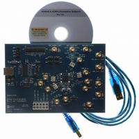
AD9549/PCBZ
Description
BOARD EVALUATION FOR AD9549
Manufacturer
Analog Devices Inc
Datasheet
1.AD9549ABCPZ.pdf
(76 pages)
Specifications of AD9549/PCBZ
Main Purpose
Timing, Clock Generator
Embedded
No
Utilized Ic / Part
AD9549
Primary Attributes
2 Inputs, 2 Outputs, VCO
Secondary Attributes
CMOS, HSTL Output Logic, Graphical User Interface
Lead Free Status / RoHS Status
Lead free / RoHS Compliant


AD9549
Phase Detector Gain Matching
Although the fine and coarse phase detectors use different means
to make a timing measurement, it is essential that both have
equivalent phase gain. Without proper gain matching, the
closed-loop dynamics of the system cannot be properly
controlled. Hence, the goal is to make PhaseGain
PhaseGain
This leads to
which simplifies to
Typically, FPFD_Gain is established first, and then PDG and
PDS are calculated. The proper choice for PDS is given by
The final value of PDS must satisfy 0 ≤ PDS ≤ 7. The proper
choice for PDG is calculated using the following equation:
The final value of PDG must satisfy 0 ≤ PDG ≤ 63. For example,
let f
PDG = 23.
Note that the AD9549 evaluation software calculates register
values that have the phase detector gains already matched.
Phase Detector Pin Connections
There are three pins associated with the phase detector that
must be connected to external components. Figure 27 shows the
recommended component values and their connections.
S
= 700 MHz and FPFD_Gain = 200; then PDS = 1 and
(
2
PDS
PDG
f
PDS
S
2
PDS
PDG
FPD
=
PFD_VRB
=
round
.
+
round
0.1µF
6
Figure 27. Phase Detector Pin Connections
)
=
PDG
(
20
16
log
10
×
=
0.1µF
10µF
10
2
7
2 (
FPFD
2
10
7
10
PDS
)
AD9549
FPFD
21
×
7
f
−
S
×
PFD_VRT
10
4
0.1µF
_
f
FPFD
7
S
Gain
2
)
_
FPFD
f
Gain
S
_
Gain
_
22
Gain
4.99kΩ
PFD_RSET
CPD
=
Rev. D | Page 22 of 76
DIGITAL LOOP FILTER COEFFICIENTS
To provide the desired flexibility, the loop filter has been
designed with three programmable coefficients (α, β, and γ).
The coefficients, along with P (where P = 2
define the response of the filter, which is given by
To evaluate the response in terms of absolute frequency, substitute
where P is the divide ratio of the P-divider, f
rate, and f is the frequency at which the function is to be evaluated.
The loop filter coefficients are determined by the AD9549
evaluation software according to three parameters:
•
•
•
The three coefficients are calculated according to parameters
via the following equations:
where:
FPFD_Gain is the value of the gain scale factor for the fine
phase detector as programmed into the I/O register map.
Note that the range of loop filter coefficients is limited as follows:
The preceding constraints on β and γ constrain the closed-loop
phase margin such that both β and γ assume negative values.
Even though β and γ are limited to negative quantities, the values as
programmed are positive. The negative sign is assumed internally.
Note that the closed-loop phase margin is limited to the range
of 0° < Φ < 90° because β and γ are negative.
F
f =
C
(
Φ
)
Φ is the desired closed-loop phase margin (0 < Φ < π/2 rad).
f
f
Note that f
0 < α < 2
−0.125 < β < 0
−0.125 < γ < 0
ω
γ
α
H
β
LOOP
DDS
=
f
(
=
=
=
=
LOOP
ω
1
f
is the desired output frequency of the DDS (Hz).
S
)
−
−
is the desired open-loop bandwidth (Hz).
1
2
+
2
LoopFilter
4
π
F
f
sin(
π
10
Pf
S
(
23
Pf
Φ
1
7
DDS
)
(~8.39 × 10
C
Φ
FPFD
β
)
tan(
=
2
can also be expressed as f
38
α
Φ
π
_
e
)
Gain
j
2
ω
6
)
+
e
jω
(
−
f
DDS
γ
+
−
(
β
f
) 2
C
−
F
e
(
γ
jω
Φ
−
)
+
PIO
β
) 1
S
DDS
(
is the DAC sample
), completely
γ
+
= f
) 1
R
(S/R).
Related parts for AD9549/PCBZ
Image
Part Number
Description
Manufacturer
Datasheet
Request
R


Part Number:
Description:
±1.7g Dual-Axis IMEMS Accelerometer Evaluation Board
Manufacturer:
Analog Devices Inc
Datasheet:

Part Number:
Description:
Inertial Sensor Evaluation System
Manufacturer:
Analog Devices Inc
Datasheet:
Part Number:
Description:
Manufacturer:
Analog Devices Inc
Datasheet:
Part Number:
Description:
Manufacturer:
Analog Devices Inc
Datasheet:
Part Number:
Description:
Manufacturer:
Analog Devices Inc
Datasheet:
Part Number:
Description:
Manufacturer:
Analog Devices Inc
Datasheet:
Part Number:
Description:
Manufacturer:
Analog Devices Inc
Datasheet:
Part Number:
Description:
Manufacturer:
Analog Devices Inc
Datasheet:
Part Number:
Description:
Manufacturer:
Analog Devices Inc
Datasheet:
Part Number:
Description:
Manufacturer:
Analog Devices Inc
Datasheet:
Part Number:
Description:
Manufacturer:
Analog Devices Inc
Datasheet:
Part Number:
Description:
Manufacturer:
Analog Devices Inc
Datasheet: