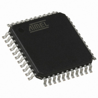
AT89C51IC2-RLTIL Atmel, AT89C51IC2-RLTIL Datasheet - Page 144

AT89C51IC2-RLTIL
Manufacturer Part Number
AT89C51IC2-RLTIL
Description
IC 8051 MCU FLASH 32K 44VQFP
Manufacturer
Atmel
Series
89Cr
Datasheet
1.AT89C51IC2-SLRIM.pdf
(147 pages)
Specifications of AT89C51IC2-RLTIL
Core Processor
8051
Core Size
8-Bit
Speed
40MHz
Connectivity
I²C, SPI, UART/USART
Peripherals
POR, PWM, WDT
Number Of I /o
34
Program Memory Size
32KB (32K x 8)
Program Memory Type
FLASH
Ram Size
1.25K x 8
Voltage - Supply (vcc/vdd)
2.7 V ~ 3.6 V
Oscillator Type
External
Operating Temperature
-40°C ~ 85°C
Package / Case
44-TQFP, 44-VQFP
Lead Free Status / RoHS Status
Contains lead / RoHS non-compliant
Eeprom Size
-
Data Converters
-
Available stocks
Company
Part Number
Manufacturer
Quantity
Price
Company:
Part Number:
AT89C51IC2-RLTIL
Manufacturer:
ATMEL
Quantity:
640
Company:
Part Number:
AT89C51IC2-RLTIL
Manufacturer:
ATMEL
Quantity:
4 116
Table of Contents
i
AT89C51IC2
Features ................................................................................................. 1
Description ............................................................................................ 2
Block Diagram ....................................................................................... 3
SFR Mapping ......................................................................................... 4
Pin Configurations .............................................................................. 10
Oscillators ........................................................................................... 14
Enhanced Features ............................................................................. 21
Dual Data Pointer Register ................................................................ 25
Expanded RAM (XRAM) ..................................................................... 27
Timer 2 ................................................................................................. 30
Programmable Counter Array PCA ................................................... 35
Serial I/O Port ...................................................................................... 47
Interrupt System ................................................................................. 58
Overview............................................................................................................. 14
Registers............................................................................................................. 14
Functional Block Diagram................................................................................... 17
Operating Modes ................................................................................................ 17
Design Considerations........................................................................................ 19
Timer 0: Clock Inputs.......................................................................................... 20
X2 Feature and OSCA Clock Generation ........................................................... 21
Auto-Reload Mode.............................................................................................. 30
Programmable Clock-Output .............................................................................. 31
PCA Capture Mode............................................................................................. 43
16-bit Software Timer/ Compare Mode............................................................... 43
High Speed Output Mode ................................................................................... 44
Pulse Width Modulator Mode.............................................................................. 45
PCA Watchdog Timer ......................................................................................... 46
Framing Error Detection ..................................................................................... 47
Automatic Address Recognition.......................................................................... 48
Baud Rate Selection for UART for mode 1 and 3............................................... 50
UART Registers.................................................................................................. 54
Registers............................................................................................................. 59
4301D–8051–02/08


